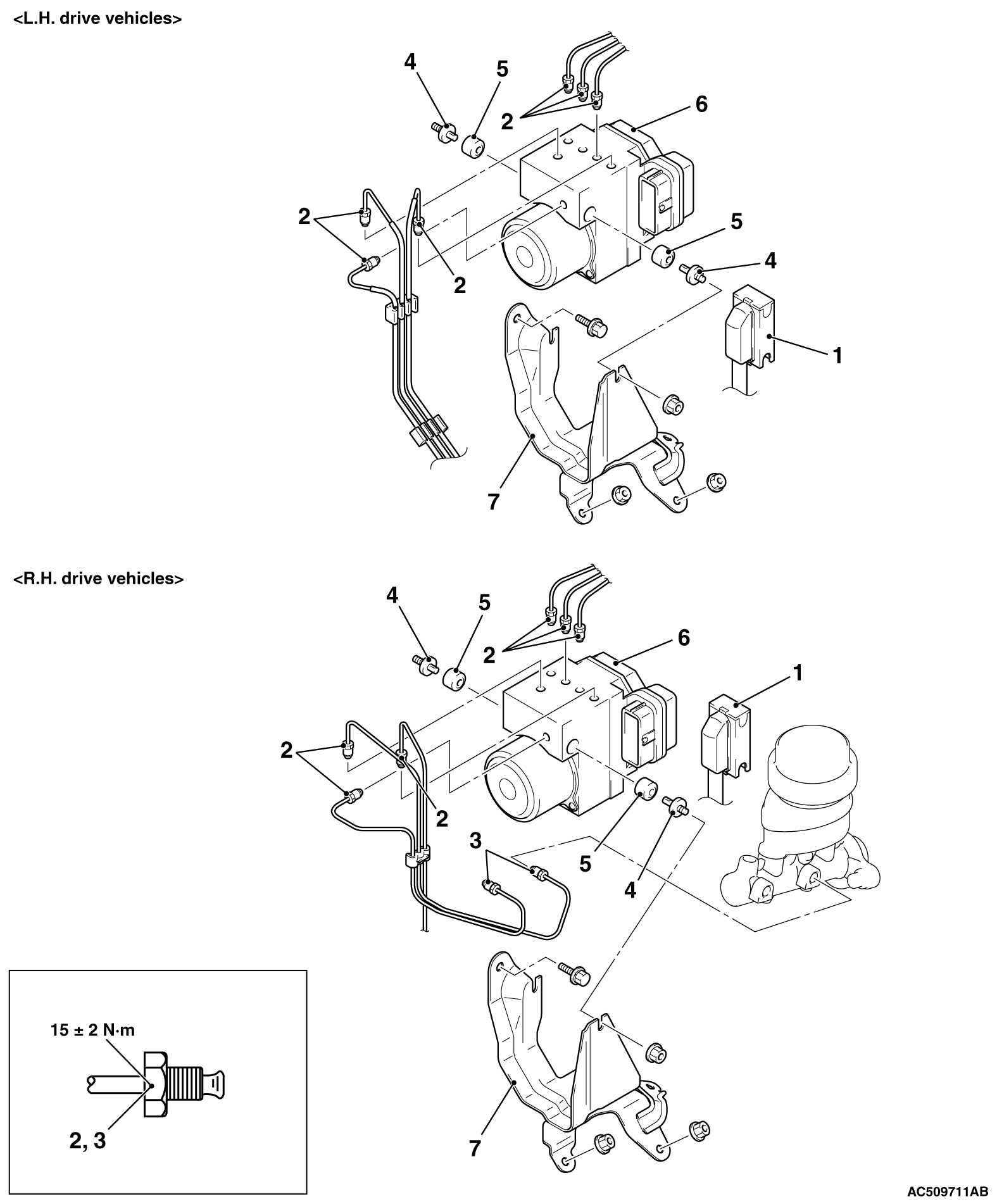
REMOVAL AND INSTALLATION


note The ASTC-ECU is integrated in the hydraulic unit.
Pre-removal Operation
  • Brake Fluid Draining
  • Battery removal <L.H. drive vehicles>
  • Air cleaner removal (Refer to GROUP 15, Air Cleaner .)

Post-installation Operation
  • Brake Fluid Filling
  • Air cleaner installation (Refer to GROUP 15, Air Cleaner .)
  • Battery installation <L.H. drive vehicles>
  • Brake Line Bleeding (Refer to GROUP 35A, On-vehicle Service - Bleeding .)
  • Hydraulic Unit Check (Refer to .)


Removal steps
<<A>>

1.
Harness connector

>>A<<
2.
Brake pipe and hydraulic unit assembly connection

>>A<<
3.
Brake pipe and master cylinder connection <R.H. drive vehicles>


4.
Bolt


5.
Insulator
<<B>>

6.
Hydraulic unit assembly (integrated with ASTC-ECU)


7.
Hydraulic unit bracket assembly

REMOVAL SERVICE POINTS


<<A>> HARNESS CONNECTOR DISCONNECTION


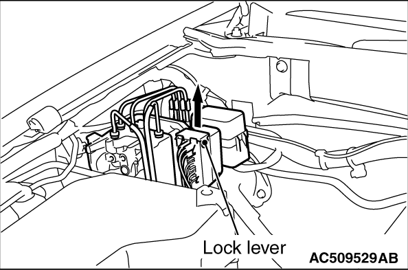
Move the lock lever of the ASTC-ECU connector as shown in the illustration, and then disconnect the harness connector.

<<B>> HYDRAULIC UNIT ASSEMBLY (INTEGRATED WITH ASTC-ECU) REMOVAL


warning The hydraulic unit is heavy. Use care when removing it.
caution
  • The hydraulic unit cannot be disassembled. Never loosen its nuts or bolts.

  • Do not drop or shock the hydraulic unit.

  • Do not turn the hydraulic unit upside down or lay it on its side.

INSTALLATION SERVICE POINT


>>A<< BRAKE PIPE CONNECTION


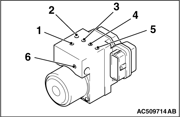
Connect the pipes to the hydraulic unit assembly as shown in the illustration.
1.From the master cylinder (primary)
2.To the front brake (LH)
3.To the rear brake (RH)
4.To the rear brake (LH)
5.To the front brake (RH)
6.From the master cylinder (secondary)