Code No. P0011: Variable Valve Timing System


OPERATION
- Refer to Code No. P1021: Oil feeder control valve system

FUNCTION
- The engine-ECU checks variable valve timing system for
abnormal conditions.
TROUBLE JUDGMENT
Check Conditions
- During engine running.
- Operation of the oil feeder control valve: OFF
- The oil feeder control valve is normal
- The camshaft position sensor is normal
- When a condition continues for 10 seconds in which the detected phase angle is on the
advanced side with respect to the angle 15° advanced from the most retarded angle.
FAIL-SAFE AND BACKUP FUNCTION
- None
PROBABLE CAUSES
- Failed oil feeder control valve
- Damage in oil feeder control valve circuit or loose connector contact
- Failed timing sprocket operation
- Clogged oil passage
- Failed inlet camshaft
- Failed engine-ECU
DIAGNOSIS PROCEDURE |
STEP 1. M.U.T.-III data list |
|
Q.
Is the check result normal?
|
 Intermittent malfunction (Refer to GROUP 00 - How to Use Troubleshooting/Inspection
Service Points - How to Cope with Intermittent Malfunctions ). Intermittent malfunction (Refer to GROUP 00 - How to Use Troubleshooting/Inspection
Service Points - How to Cope with Intermittent Malfunctions ). |
|
 Go to Step 2 . Go to Step 2 . |
|
STEP 2. Check oil feeder control valve itself. |
|
Q.
Is the check result normal?
|
| Go to Step 3 . |
|
| Replace the oil feeder control valve. |
|
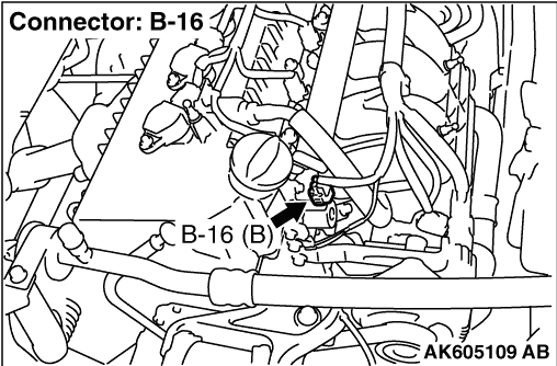
STEP 3. Connector check: B-16 oil feeder control valve connector and B-08 engine-ECU connector |
Q.
Are the check results normal?
|
| Go to Step 4 . |
|
| Repair or replace the connector. |
|
STEP 4. Check harness between B-16 (terminal No. 2) oil feeder control valve connector and B-08 (terminal No. 1) engine-ECU connector. |
|
Q.
Is the check result normal?
|
| Go to Step 5 . |
|
| Repair the damaged harness wire. |
|
STEP 5. Connector check: A-33X engine control relay connector |
Q.
Is the check result normal?
|
| Go to Step 6 . |
|
| Repair or replace the connector. |
|
STEP 6. Check harness between A-33X (terminal No. 2) engine control relay connector and B-16 (terminal No. 1) oil feeder control valve connector. |
|
|
Q.
Is the check result normal?
|
| Go to Step 7 . |
|
| Repair the damaged harness wire. |
|
STEP 7. Check camshaft sensing portion. |
Q.
Is the check result normal?
|
| Go to Step 8 . |
|
| Replace the inlet camshaft. |
|
STEP 8. Check oil passage of variable valve timing control system for being clogged. |
Q.
Is the check result normal?
|
| Go to Step 9 . |
|
| Repair |
|
STEP 9. Check variable valve timing sprocket operation mechanism for being stuck. |
|
Q.
Is the check result normal?
|
| Go to Step 10 . |
|
| Repair |
|
STEP 10. M.U.T.-III diagnosis code |
|
Q.
Is diagnosis code set?
|
| Replace the engine-ECU. |
|
| Intermittent malfunction (Refer to GROUP 00 - How to Use Troubleshooting/Inspection
Service Points - How to Cope with Intermittent Malfunctions ). |
|