Inspection Procedure 2: Neither Right nor Left Automatic Levelling Operates.
| caution | Before replacing the ECU, ensure that the power supply circuit, the earth circuit and the communication circuit are normal. |
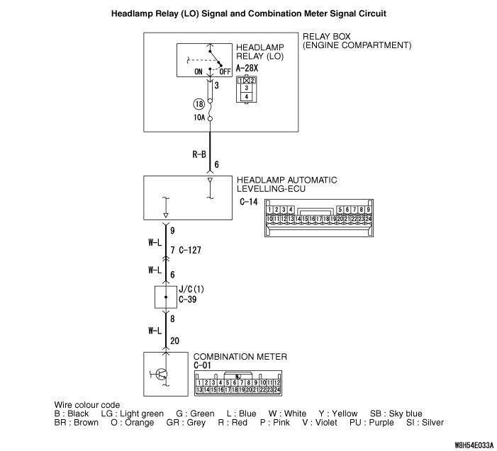


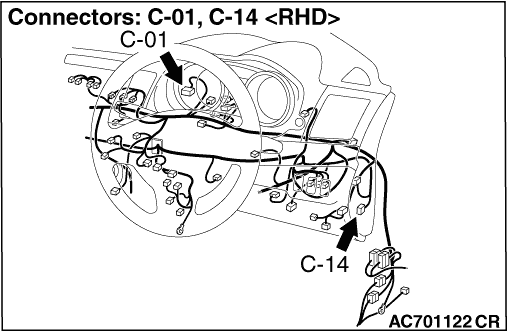

OPERATION
| note | The automatic levelling during driving at a constant speed operates only once after starting driving. The automatic levelling does not work if the vehicle pitch angle during driving at a constant speed and the vehicle pitch angle when the vehicle is stopped are the same. |
COMMENTS ON TROUBLE SYMPTOM
PROBABLE CAUSES
- Malfunction of the headlamp automatic levelling-ECU
- Malfunction of combination meter
- Damaged harness wires and connectors
DIAGNOSIS PROCEDURE
STEP 1. Check the diagnosis code.

Q.
Is the headlamp automatic levelling warning display is blinking under normal condition?


STEP 2. Check the operation of the headlamps.
Q.
Is the check result normal?
STEP 3. Combination meter check
Q.
Does the speedometer operate?

STEP 4. Connector check: C-14 headlamp automatic levelling-ECU connector
Q.
Is the check result normal?
STEP 5. Voltage measurement at the C-14 headlamp automatic levelling-ECU connector
| (1)Disconnect the connector, and measure at the wiring harness-side connector. |
| (2)Turn ON the headlamp switch. |
| (3)Voltage between the C-14 headlamp automatic levelling-ECU connector terminal No. 6 and the body earth OK: System voltage |
Q.
Is the check result normal?
STEP 6. Wiring harness check between the C-14 headlamp automatic levelling-ECU connector terminal No. 6 and the A-28X headlamp relay (LO) connector terminal No. 3
- Check the communication lines for open circuit and short circuit.
Q.
Is the check result normal?
STEP 7. Connector check: C-01 combination meter connector
Q.
Is the check result normal?
STEP 8. Wiring harness check between the C-14 headlamp automatic levelling-ECU connector terminal No. 9 and the C-01 combination meter connector terminal No. 20
| note | Prior to the wiring harness inspection, check the intermediate connector C-127, and the joint connector C-39, and repair if necessary. |
- Check the communication lines for open circuit and short circuit.
Q.
Is the check result normal?
- Go to Step 9.
STEP 9. Retest the system
Q.
Is the check result normal?
