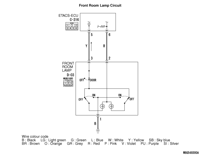
Inspection Procedure 1: The Front Room Lamp does not Illuminate Normally.
| caution | Whenever the ECU is replaced, ensure that the power supply circuit, the earth circuit and the communication circuit are normal. |
OPERATION
- Ignition switch (IG1)
- Key reminder switch
- Door switches
- Front door lock actuator (driver’s side)
COMMENTS ON TROUBLE SYMPTOM
PROBABLE CAUSES
- Malfunction of the key reminder switch
- Malfunction of door switch
- Malfunction of the front door lock actuator (driver’s side)
- Malfunction of front room lamp
- Malfunction of the ETACS-ECU
- Damaged harness wires and connectors
DIAGNOSIS PROCEDURE
STEP 1. Rear room lamp operation check
Q.
Is the check result normal?


STEP 2. M.U.T.-III diagnosis code
Q.
Is the diagnosis code set?


STEP 3. M.U.T.-III data list
- Turn the ignition switch to the LOCK (OFF) position.
- Remove the ignition key from the ignition key cylinder.
- Open each door.
|
Q.
Is the check result normal?
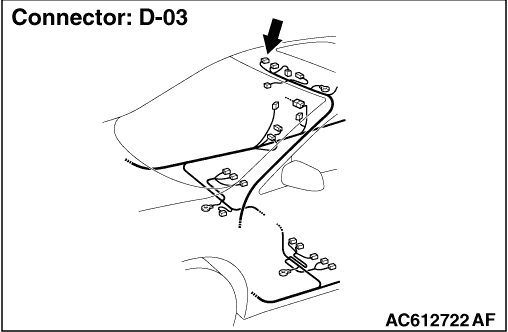
STEP 4. Connector check: D-03 front room lamp connector
Q.
Is the check result normal?

STEP 5. Front room lamp bulb check
Q.
Is the check result normal?
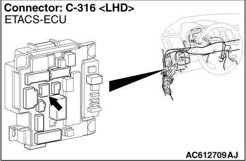
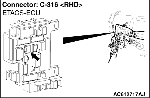
STEP 6. Connector check: C-316 ETACS-ECU connector
Q.
Is the check result normal?
STEP 7. Wiring harness check between the D-03 front room lamp connector terminal No. 2/3 and the C-316 ETACS-ECU connector terminal No. 6/5
- Check the input/output line for open circuit.
Q.
Is the check result normal?
STEP 8. Connector check: D-03 front room lamp connector
Q.
Is the check result normal?
STEP 9. Wiring harness check between the D-03 front room lamp connector terminal No. 1 and the body earth
- Check the output lines for open circuit.
Q.
Is the check result normal?
STEP 10. Retest the system
Q.
Is the check result normal?