EXTERIOR LAMPS
Construction diagram
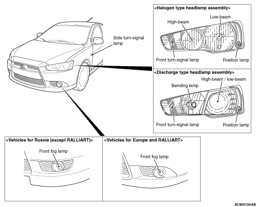
- With the headlamp assembly, the following two types have been provided: Halogen bulbs are equipped for high-beam and low-beam; discharge bulbs are equipped for high-beam and low-beam.
- For the halogen type headlamp assembly, the four-headlamp incorporating the headlamp (low-beam), the headlamp (high-beam), the front turn-signal lamp and the position lamp has been adopted.
- For discharge type headlamp assembly, the two-headlamp incorporating the headlamp (high-beam / low-beam), the bending lamp, the front turn-signal lamp and the position lamp has been adopted.
- Switching of the high-beam and low-beam illumination of the discharge type headlamp is controlled by moving the lightproof board in the projector unit according to the signal from the column switch (lighting switch).
- For the low-beam of the headlamp, the headlamp manual levelling system <Vehicles with halogen type headlamp> (Refer to
 .) and the headlamp automatic levelling system <Vehicles with discharge type headlamp> (Refer to .) have been adopted so that the height adjustment of the optical axis can be performed depending on the vehicle load status.
- For the bending lamp, AFS (Refer to .) has been adopted so that the bending lamp, linked with the steering wheel operation, turns ON/OFF its light which beams the cornering direction while vehicle driving.
- The front fog lamp with no-cut lens has been adopted for better appearance. <Standard: INTENSE and RALLIART, Option: INFORM and INVITE>
- The side turn-signal lamps have been installed to the fender.
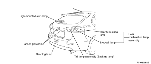
- The rear combination lamp assembly are integrated with the stop/tail lamp and the rear turn-signal lamp.
- The tail lamp assembly are integrated with the back-up lamp.
- The rear fog lamp has been installed at the centre of the rear bumper.
- The LED type high-mounted stop lamp has been installed in the lower part of the tailgate window glass.
- The licence plate lamp has been installed in the upper part of the licence plate.
- The lighting system is provided with auto lamp function (Refer to ), headlamp automatic-shutdown function and daytime running lamp function (Refer to Function and Control by ETACS-ECU ).
- For the flasher timer function of the turn-signal lamps, the comfort flasher function has been adopted to improve the operability when changing lanes. When the turn-signal lamp switch (lighting switch) is operated for a short time, this function flashes the turn-signal lamp of the operated direction three times. The ESS (Emergency Stop signal System), which informs the following car that the driver is applying the brake suddenly, has also been adopted. (Refer to Function and Control by ETACS-ECU ).
Specifications
| Item |
Specification |
|
| Headlamp assembly <Vehicles with halogen type headlamp> |
High-beam W <halogen headlamp> |
60 (HB3) |
| Low-beam W <halogen headlamp> |
51 (HB4) |
|
| Position lamp W |
5 (W5W) |
|
| Front turn-signal lamp W |
21 (WY21W) |
|
| Headlamp assembly <Vehicles with discharge type headlamp> |
High-beam / low-beam W <discharge headlamp> |
35 (D2S) |
| Bending lamp W |
55 (H11) |
|
| Position lamp W |
5 (W5W) |
|
| Front turn-signal lamp W |
21 (WY21W) |
|
| Front fog lamp W |
55 (H11) |
|
| Side turn-signal lamp W |
5 |
|
| Rear combination lamp assembly |
Stop/tail lamp W |
21 / 5 (W21 / 5W) |
| Rear turn-signal lamp W |
21 (WY21W) |
|
| Tail lamp assembly |
Back-up lamp W |
16 (W16W) |
| Rear fog lamp W |
21 (W21W) |
|
| High-mounted stop lamp |
LED type |
|
| Licence plate lamp W |
5 (W5W) |
|
| note | The brackets ( ) show the bulb type. |
Headlamp manual levelling system |
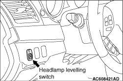 |
The beam direction of the headlamps changes according to the number of passengers and the amount of load. The headlamp manual levelling function is a system that allows the driver to change the direction of headlamp beam so that the drivers of oncoming cars are not dazzled by the headlamps. The headlamp levelling switch allows changing the direction in five steps: 0 to 4. |
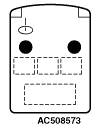
Relationship between the switch positions and the number of passengers/loads
| Passenger and load |
 |
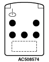 |
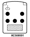 |
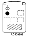 |
| One or two passengers |
Five passengers |
Five passengers and heavy loads |
Driver and heavy loads |
|
| Switch position |
0 |
1 |
2 |
3 |
|
Operation
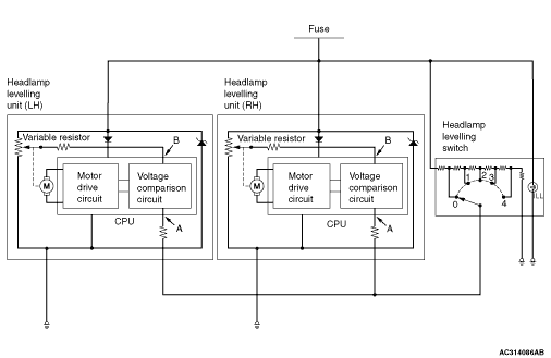
1.
2.
3.
Headlamp automatic levelling system
Function
| Vehicle condition |
Control content |
| When parking |
The headlamp automatic levelling-ECU calculates the vehicle pitch angle from the height sensor values according to the change in load resulting from getting on/off or loading/unloading to control the beam direction. |
| When driving at a constant speed |
When a vehicle starts on curb, the travelling vehicle posture changes from the posture during parking, so that the beam direction changes. To control the improper beam direction caused by such vehicle posture change, the headlamp automatic levelling-ECU calculates the vehicle pitch angle based on the average of height sensor values obtained for 12 seconds after the vehicle speed becomes constant. This beam direction control while driving at a constant speed is performed only once between a vehicle stop and the next stop. If driving is started at a constant speed on the gravel or rough road, to prevent unnecessary control resulting from detection of road uneven surface, the beam direction control is launched after the driving speed becomes constant on pavement. |
Construction diagram
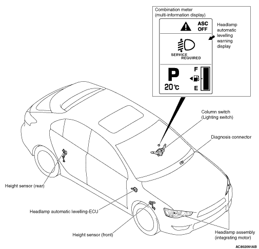
System component and function
| Parts name |
Functional description |
| Column switch (Lighting switch) |
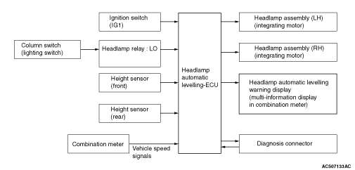
When the lighting switch is set to the headlamp position, the headlamp relay (LO) inside the engine compartment turns ON to transmit the signal to the headlamp automatic levelling-ECU. |
| Height sensor (front) |
Detects the elongation/contraction of the front suspension and transmits the signal to the headlamp automatic levelling-ECU. |
| Height sensor (rear) |
Detects the elongation/contraction of the rear suspension and transmits the signal to the headlamp automatic levelling-ECU. |
| Combination meter |
Transmits vehicle speed signals to the headlamp automatic levelling-ECU. |
| Headlamp assembly (integrating motor) |
Drives the headlamp reflector by receiving signals from the headlamp automatic levelling-ECU. |
| Headlamp automatic levelling warning display |
Lights up on the multi-information display in the combination meter to warn the driver that an abnormality occurs in the headlamp automatic levelling system. |
| Headlamp automatic levelling-ECU |
Controls the motor integrated in the headlamp assembly based on the signals form switches and sensors to control the beam direction according to the vehicle posture. |
| Diagnosis connector |
Outputs diagnosis codes. |
System block diagram
Fail-safe function
| Trouble spot |
Trouble condition |
Headlamp automatic levelling warning display |
Countermeasures for trouble |
| Height sensor |
Open or short circuit |
Warning display |
Control stop |
| Vehicle speed signal |
Open or short circuit |
- |
Judges as parking, and continues control. |
| Motor (integrated in headlamp assembly) |
Open circuit |
- |
Control stop |
| Short |
Warning display |
Control stop |
|
| Headlamp automatic levelling-ECU |
Open or short circuit |
- |
Control stop |
| ECU is out of control |
- |
Program reset by ECU self-diagnosis |
|
| Headlamp signal |
Open or short circuit |
- |
Control stop |
AFS (Adaptive front-lighting system)
Operational Description
- The ignition switch is in the ON position.
- The shift lever <M/T and TC-SST> or the selector lever <A/T and CVT> is in the position other than the reverse position.
- The lighting switch is in the HEAD or AUTO position. (LO of the headlamp relay is ON.)
- The AFS control switch is OFF. (The AFS OFF indicator lamp of the combination meter is OFF.)
- The vehicle speed is approximately 80 km/h or less.
- The steering wheel is turned toward either right or left from the neutral position. (When the bending lamp is ON, the rotation angle of the steering wheel changes depending on the vehicle speed.)
- The ignition switch is turned to the OFF or ACC position.
- The shift lever <M/T and TS-SST> or the selector lever <A/T and CVT> is in the reverse position.
- The lighting switch is in the position other than the HEAD or AUTO position. (LO of the headlamp relay is OFF.)
- The AFS is turned ON by the AFS control switch. (The AFS OFF indicator lamp of the combination meter is ON.)
- The vehicle speed is approximately 100 km/h or more.
- The rotation angle of the steering wheel is near to the neutral position (either right or left).
- Either right or left bending lamp is turned ON for 15 minutes or longer continuously.
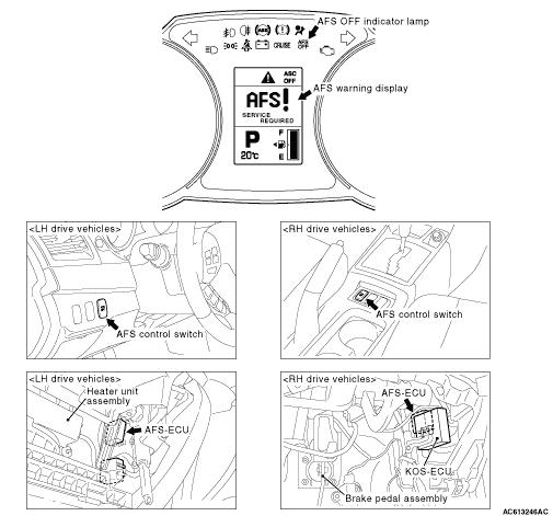
SYSTEM COMPONENT AND FUNCTION
| Parts name |
Functional description |
| AFS control switch |
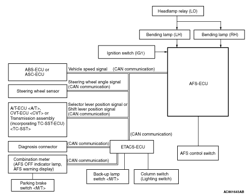
Transmits the AFS ON/OFF signal to AFS-ECU |
| Back-up lamp switch <M/T> |
Transmits the reverse signal to AFS-ECU. |
| Column switch (Lighting switch) |
Transmits the lighting switch signal to ETACS-ECU to turn ON/OFF the headlamp relay (LO). |
| Parking brake switch <M/T> |
Transmits the parking brake switch signal to AFS-ECU. |
| Combination meter (AFS OFF indicator lamp) |
When AFS is turned OFF by the AFS control switch, turns OFF the AFS OFF indicator lamp by the signal from AFS-ECU to inform the driver of the AFS deactivation. When an AFS abnormality occurs, the AFS OFF indicator lamp flashes to inform the driver of the AFS abnormality. |
| Combination meter (AFS warning display) |
When an AFS abnormality occurs, indicates the warnings on the multi-information display of combination meter to inform the driver of the AFS abnormality. |
| Headlamp relay (LO) |
When the headlamp relay (LO) is ON, supplies the power to the bending lamp. |
| Steering wheel sensor |
Detects the rotation angle of the steering wheel and transmits the signal to AFS-ECU. |
| A/T-ECU, CVT-ECU or transmission assembly (incorporating TC-SST-ECU) <TC-SST> |
Transmits the selector lever position signal to AFS-ECU. |
| ABS-ECU or ASC-ECU |
Transmits the vehicle speed signal to AFS-ECU. |
| AFS-ECU |
According to the signals from the switches, ECUs, and steering wheel sensors, turns ON/OFF the bending lamp. |
| Diagnosis connector |
Outputs diagnosis codes. |
System block diagram
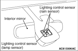
Auto lamp function |
 |
|