|
|
- Refer to Data List Reference Table
 . .
- Item 5: Intake air temperature sensor
- Item 6: Engine coolant temperature sensor
- Item 8: Manifold absolute pressure sensor
- Item 10: Air flow sensor
|
|
|
Q.
Are the check results normal?
|
|
|
 Perform the diagnosis code classified check procedure for the sensor that has
shown an abnormal data value (Refer to Inspection Chart for Diagnosis Code ). Perform the diagnosis code classified check procedure for the sensor that has
shown an abnormal data value (Refer to Inspection Chart for Diagnosis Code ).
|
|
|
|
|
|
- Refer to Data List Reference Table .
- Item BB: Barometric pressure sensor
|
|
|
Q.
Is the check result normal?
|
|
|
Q.
Is the check result normal?
|
|
|
Repair or replace the connector.
|
|
|
|
|
|
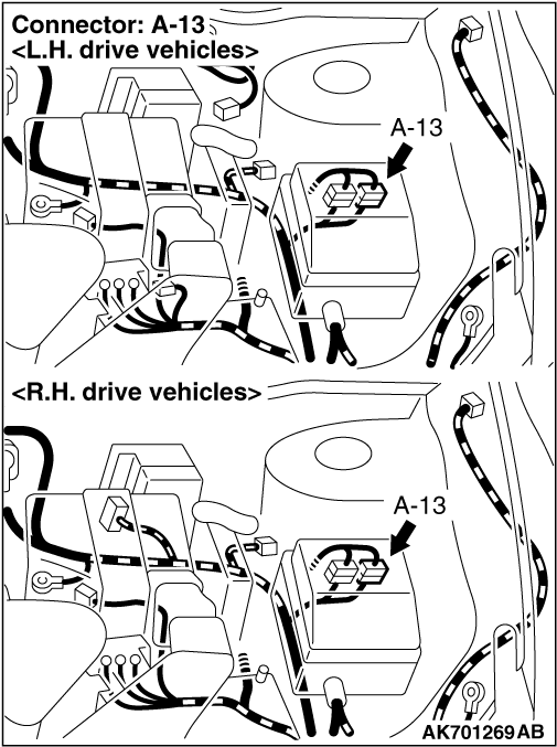
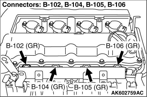
- Check and repair harness between A-13 (terminal No.
7) intermediate connector and B-102 (terminal No. 1) No. 1 injector connector.
- Check and repair harness between A-13 (terminal No. 7) intermediate connector and
B-104 (terminal No. 1) No. 2 injector connector.
- Check and repair harness between A-13 (terminal No. 7) intermediate connector and
B-105 (terminal No. 1) No. 3 injector connector.
- Check and repair harness between A-13 (terminal No. 7) intermediate connector and
B-106 (terminal No. 1) No. 4 injector connector.
- Check power supply line for damage.
|
|
|
Q.
Are the check results normal?
|
|
|
Repair the damaged harness wire.
|
|
|
|
|
|
- Check Injector itself (Refer to Injector Check ).
|
|
|
Q.
Is the check result normal?
|
|
|
- Fuel pressure measurement (Refer to Fuel Pressure Test ).
|
|
|
Q.
Is the check result normal?
|
|
|
- After replacing the injector, re-check the trouble symptoms.
|
|
|
Q.
Is the check result normal?
|
 Go to Step 2 .