STRUCTURE
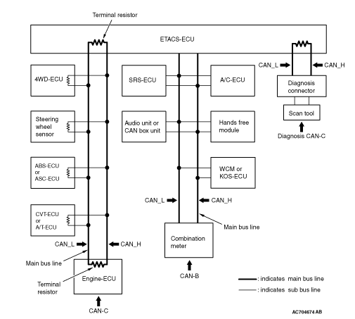
- A gateway function has been integrated to ETACS-ECU as the network central ECU.
- The CAN system consists of the following three networks: CAN-B (middle-speed body network), CAN-C (high-speed power train network), and the diagnosis CAN-C (diagnosis exclusive network). Each ECU is connected to one of the networks depending on its functions.
- The CAN bus line consists of two lines, CAN_L and CAN_H (CAN Low and CAN High, respectively), as well as two terminal resistors (A twisted-pair cable, highly resistant to noise, is used for the communications line).
- The CAN bus line connecting two dominant ECUs is the main bus line, and the CAN bus line connecting each ECU is the sub-bus line.
- With CAN-C, the terminal resistors are incorporated in ECU. Resistors with approximately 120 Ω is used for the dominant ECU, and that with 4.7 kΩ is used for the non-dominant ECU.
note - Dominant ECU: ETACS-ECU and engine-ECU
- Non-dominant ECU: ECU and sensor on CAN-C network, excluding ETACS-ECU and engine ECU
- Dominant ECU: ETACS-ECU and engine-ECU
- To the CAN bus line, ECU, sensor, and diagnosis connector are connected as follows for each network.
- WCM <vehicles without KOS>
- KOS-ECU <vehicles with KOS>
- SRS-ECU
- A/C-ECU
- Audio unit <vehicles with audio unit> or CAN box <vehicles with MMCS>
- Combination meter
- 4WD-ECU
- Steering wheel sensor
- ABS-ECU <vehicles without ASC> or ASC-ECU <vehicles with ASC>
- CVT-ECU <vehicles with CVT> or A/T-ECU <vehicles with A/T>
- Engine-ECU <2000, 2400 and 3000>
- Diagnosis connector