
|
1.Use special tool Oil filter wrench (MB991396) to remove the oil filter.
|
|
|
1.Remove oil pan tightening bolts.
|

|
2.| caution |
Lightly tap the oil pan FIPG cutter to drive in, taking care not to damage
the ladder frame and oil pan sealed area.
|
Lightly tap special tool Oil pan FIPG cutter (MD998727) to drive in the illustrated groove
of the oil pan and ladder frame.
|

|
3.Lightly tap and slide special tool Oil pan FIPG cutter (MD998727) to remove the oil pan.
|

|
If the timing chain case is difficult to remove, insert a hammer handle as shown in the
illustration and lightly pry it.
|
|
|
1.| caution |
- Completely remove all the old liquid gasket, which might
be remaining in the installation hole, the O-ring groove or among the components such as the
cylinder head gasket.
- Sufficiently check that there is no residual oil on the place where degreasing is
performed. If fingerprints are left, do not touch it with bare hands after the degreasing, since
the oils from your fingers will harm the seal ability.
|
Completely remove liquid gasket adhering to the timing chain case, cylinder block and
cylinder head.
|
|
|
2.Degrease the surface where the liquid gasket is applied and the contact surface between
the cylinder block and the cylinder head.
|
|
|
3.
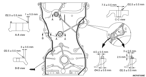
| caution |
Install the timing chain case within three minutes after applying
the liquid gasket.
|
Apply liquid gasket of 2.5 ± 0.5 mm in thickness to the timing chain case. For
the place "D" shown in the illustration, however, apply the liquid gasket whose diameter is
4.5 ± 0.5 mm or pile up the liquid gasket of 2.5 ± 0.5 mm as shown in the
illustration.
Specified sealant:
ThreeBond 1217G or equivalent
|

|
4.The engine oil staying at the cylinder gasket oozes to the 3-plane contact surface described
in Step 2 and 3. Swiftly apply the liquid gasket to this area after degreasing.
Specified sealant:
ThreeBond 1217G or equivalent
|

|
5.Tighten timing chain case mounting bolts to the specified torque.
Tightening torque
A: 24 ± 4 N·m
B: 10 ± 2 N·m
C: 10 ± 2 N·m
D: 13 ± 1 N·m
|
|
|
1.Apply a small amount of engine oil to the entire inner diameter of the front oil seal
lip.
|

|
| caution |
The front oil seal must not be a strong press fit. The strong press
fit can possibly cause the oil leakage, damaging the front oil seal.
|
2.Use special tool Bush remover and installer base (MB991448) in order to press-fit
the front oil seal into the timing chain case as shown in the illustration.
|
|
|
1.Completely remove liquid gasket adhering to the cylinder block and oil pan.
|

|
| caution |
Install the oil pan within three minutes after liquid gasket
is applied.
|
2.Apply liquid gasket of Φ2.5 ± 0.5 mm of thickness in diameter to
the illustrated area of the oil pan.
Specified sealant:
ThreeBond 1217G or equivalent
3.Tighten the oil pan to the specified torque of 10 ± 2 N·m (M6) and
29 ± 2 N·m (M8).
|
|
|
1.Completely remove liquid gasket adhering to the cylinder head cover, timing chain
case and cylinder head.
|
|
|
2.Degrease the surface where the liquid gasket is applied and the contact.
|

|
| caution |
Install the cylinder head cover immediately after liquid gasket
is applied.
|
3.Appropriately use a minimum amount of sealant. Besides, be careful not to allow sealant
to squeeze out from the application area.
Apply liquid gasket of 4 mm of thickness in diameter.
Specified sealant:
ThreeBond 1217G or equivalent
|

|
4.5.Tighten the cylinder head cover to the tightening torque of 3.0 ± 1.0 N·m
in the order shown in the illustration.
6.Then, tighten it to the specified torque of 5.5 ± 0.5 N·m in the same
order.
|
|
|
1.Clean the oil filter mounting surface of the ladder frame.
|

|
2.Apply engine oil to the O-ring of the oil filter.
|
|
| caution |
Use special tool Filter wrench (MB991396) to install the
oil filter. Tightening it by hand causes oil leakage due to lack of torque.
|
3.Screw in the oil filter. When the O-ring contacts the mounting surface, use a filter
wrench to tighten it 1 turns (14 ± 2 N·m).
|

