|
|
1.Remove the fuel injector and common rail assembly and also the rocker cover assembly
(Refer to  ). ).
|

|
2.
| caution |
The crankshaft should always be turned in a clockwise direction.
|
Align the camshaft sprocket timing marks and set the No. 1 cylinder at compression stroke
top dead centre.
|


|
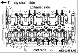
3.For the portions with the arrows shown below, measure and adjust the valve clearances
by using the following procedures.
< Sides except inlet side without MIVEC >
1.) By using the thickness gauge, measure the clearance between the cam and roller.
Standard value (cold engine):
Inlet valve: 0.08 ± 0.03 mm
Exhaust valve: 0.16 ± 0.03 mm
2.) By using the thickness gauge, measure the clearance between
the cam and roller.
| caution |
Pay special attention that the tightening torque is not beyond
this valve. If the tightening torque is beyond the valve, the valve stem would possibly bend.
|
3.)While holding the adjusting screw with a screwdriver
to prevent it from turning, tighten the lock nut to the specified torque using the special tool,
valve adjusting socket.
Special tool (valve adjusting socket):
Inlet side: MB991477
Exhaust side: MB992046
Tightening torque:
Inlet side: 9 ± 1 N·m
Exhaust side: 9.8 ± 1 N·m
< Inlet side without MIVEC>
1.) By using the special tool MB992852 (valve adjusting feeling gauge), check that
the clearance is within the standard value between the valve stem and adjusting screw.
Standard value: 0.14 ± 0.03 mm
2.)If the valve clearance is not as specified, loosen
the adjusting screw lock nut and adjust the clearance using the special tool MB992852 (valve
adjusting feeling gauge) between the valve stem and the adjusting screw while turning the adjusting
screw.
| caution |
Pay special attention that the tightening torque is not beyond
this valve. If the tightening torque is beyond the valve, the valve stem would possibly bend.
|
3.)While holding the adjusting screw with a screwdriver
to prevent it from turning, tighten the lock nut to the specified torque using the special tool
MB991477 (valve adjusting socket).
Tightening torque: 9 ± 1 N·m
|
|
4.Turn the crankshaft 360° clockwise to bring No. 4 cylinder to the top dead centre
position.
5.For the portions with the arrows shown below, measure and adjust the valve clearances
by using the same procedures as ones in the Step 3.
6.Install the rocker cover assembly and also the fuel injector and common rail assembly
(Refer to ).
7.Confirm there is no fuel leak from the joint for the injection pipe (Refer to GROUP
13B - On vehicle Service - Fuel Line Leak Check ).
|