|
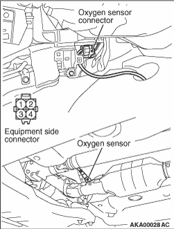
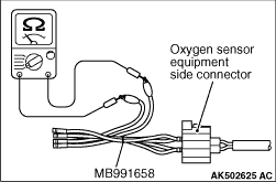
1.Disconnect the oxygen sensor connector and connect the special tool test harness (MB991658)
to the connector on the oxygen sensor side.
|
|
2.Measure the resistance between terminal No. 1 and No. 2 of the oxygen sensor connector.
Standard value: 4.5 - 8.0 Ω (at 20°C)
3.If the resistance deviates from the standard value, replace the oxygen sensor.
4.Warm up the engine until the engine coolant temperature is 80°C or higher.
5.Perform a racing for 5 minutes or more with the engine speed of 2,000 r/min.
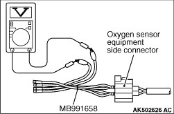
6.Connect the digital voltmeter between terminal No. 3 and No. 4.
7.While repeatedly racing the engine, measure the oxygen sensor output voltage.
Standard value:
|
|
Engine
|
Oxygen sensor output voltage
|
Remarks
|
When racing the engine
|
0.6 - 1.0 V
|
If you make the air-fuel ratio rich by racing the engine repeatedly,
a normal oxygen sensor will output a voltage of 0.6 - 1.0 V.
|
|
| caution |
- Be very careful when connecting the jumper wire,
or incorrect connection can damage the oxygen sensor.
- Exercise sufficient care so as not to apply voltage exceeding 8 V onto the oxygen
sensor heater; otherwise the heater may be damaged.
|
| note |
If the temperature of sensing area does not reach the high temperature (of approximately
400°C or more) even though the oxygen sensor is normal, the output voltage would be
possibly low in spite of the rich air-fuel ratio.
Therefore, if the output voltage is low, use a jumper wire to connect the terminal No.
1 and No. 2 of the oxygen sensor with the (+) and (-) terminals of 8 V power
supply respectively, then check the voltage again.
|
8.If the voltage deviates from the standard value, replace the oxygen sensor.
| note |
For removal and installation of the oxygen sensor, refer to GROUP 15 - Exhaust
Pipe and Main Muffler - Removal and Installation  . .
|
|