GENERAL INFORMATION
FUEL INJECTION CONTROL
IDLE SPEED CONTROL
SELF-DIAGNOSIS FUNCTION
- When an abnormality is detected in any of the sensors or actuators, the engine
warning lamp illuminates to warn the driver.
- When an abnormality is detected in any of the sensors or actuators, a diagnosis
code number corresponding to the problem which occurred is output.
- The RAM data relating to the sensors and actuators which is stored in the engine-ECU
can be read using the M.U.T.-III. In addition, the actuator can be force-driven under certain conditions.
OTHER CONTROL FUNCTIONS
- 1. Power Supply Control
When the ignition switch ON signal is input by the ignition switch, the engine-ECU turns ON the power transistor for controlling the engine control relay. As a result, current flows through the coil in the engine control relay, causing the relay switch to turn ON and supply power to the sensors and actuators.
- 2. Glow Control
(Refer to GROUP 16 - Glow System <4N1> - General Information
 ).
).- 3. EGR Control
[Refer to GROUP 17 - Emission Control <DIESEL> - Exhaust Gas Recirculation (EGR) System- General Information (EGR system)
].- 4. A/C compressor Relay Control
Turns the compressor clutch of the A/C ON and OFF.
- 5. DPF System Control
[Refer to GROUP 17 - Emission Control <DIESEL> - Diesel Particulate Filter (DPF) System - General Information (DPF system)
].- 6. Variable Geometry Turbocharger Control
Performing the duty control over the variable geometry control solenoid valve, the engine-ECU opens and closes the nozzle vane located in the turbocharger assembly. This allows the boost pressure to be obtained in accordance with the engine operation.
- 7. Fuel Pump Control
Turns the fuel pump relay ON so that current is supplied to the fuel pump while the engine is cranking or running.
- 8. Oil Feeder Control Valve Control <MIVEC>
The engine-ECU effects duty cycle control on the oil feeder control valve, in accordance with the engine speed. This regulates the supply of engine oil to the intake rocker shaft, which switches the cams.
- 9. Alternator Output Current Control
Prevents the alternator output current from increasing suddenly and the idle speed from varying such as when the headlamp is turned on.
- Auto Stop Prohibition Control
When one or more of following conditions are satisfied during idling, the engine-ECU should send the auto stop prohibition signal to the AS&G-ECU.
- The engine coolant temperature is lower than approximately
50°C or is higher than approximately 90°C.
- The intake air temperature is higher than approximately 50°C.
- When one or more of the following conditions are satisfied, the vehicle is in "auto
stop prohibition status" by electrical load.
- The amount of the vehicle current consumption is more
than the specified value.
- The power generation control is in the forcible full charge mode.
- Forcible Auto Start Request Control
When one or more of following conditions are satisfied during the auto stop, the engine-ECU should send the engine start request signal to the AS&G-ECU.
- The engine coolant temperature is lower than approximately
40 °C.
- The amount of the vehicle current consumption is more than the specified value.
- DTC P1608 is detected.
- When the DPF regeneration is requested.
|
|||||||||||||||||||||||||||||||||||||||||||||||||||||||||||||||||||||||||||
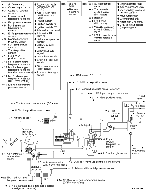
FUEL INJECTION SYSTEM DIAGRAM