STARTER MOTOR ASSEMBLY INSPECTION <4N1>
PINION GAP ADJUSTMENT |
 |
1.Disconnect the field coil wire from the M-terminal of the magnetic switch. 2.Connect a 12-volt battery between the S-terminal and M-terminal. 3.
|
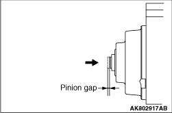 |
4.Push the pinion back with a finger and measure the pinion stroke (the travel along which
the pinion is pushed back). This is the pinion gap. Standard value: 0.5 - 2.0 mm |
 |
5.If the pinion gap is not up to specification, adjust by adding or removing fibre washers
between the magnetic switch and the front bracket. Using more washers makes the gap smaller. |
MAGNETIC SWITCH PULL-IN TEST |
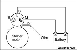 |
1.Disconnect the field coil wire from the M-terminal of the magnetic switch.
3.If the pinion moves out, the pull-in coil is good. If it doesn’t, replace the magnetic switch. |
MAGNETIC SWITCH HOLD-IN TEST |
 |
1.Disconnect the field coil wire from the M-terminal of the magnetic switch. 2.
3.Manually pull out the pinion as far as the pinion stopper position. 4.If the pinion remains out, everything is in order. If the pinion moves in, the hold-in circuit is open. Replace the magnetic switch. |
FREE RUNNING TEST |
 |
1.Place the starter motor in a vise equipped with soft jaws and connect a fully-charged
12-volt battery to the starter motor as follows: 2.Connect a test ammeter (150-ampere scale or more) and carbon pile rheostat in series between the positive battery terminal and starter motor terminal. 3.Connect a voltmeter (15-volt scale) across the starter motor. 4.Rotate the rheostat to full-resistance position. 5.Connect the battery cable from the negative battery terminal to the starter motor body. 6.Adjust the rheostat until the battery positive voltage shown on the voltmeter is 11 V. 7.Confirm that the maximum amperage is within the specifications and that the starter motor turns smoothly and freely. Current:
maximum 140 A <Vehicles with AS&G system> |
MAGNETIC SWITCH RETURN TEST |
 |
1.Disconnect the field coil wire from the M-terminal of the magnetic switch. 2.
3.
|