|
|
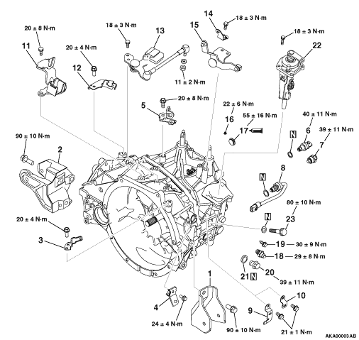
1.Remove the transfer<
W6MBA >.
|
|
|
2.Remove the roll stopper bracket.
|
|
|
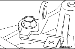
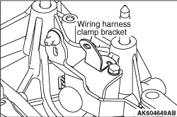
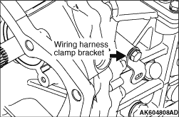
3.Remove the wiring harness clamp bracket.
|
|
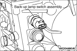
4.Remove the back-up lamp switch assembly.
|
|
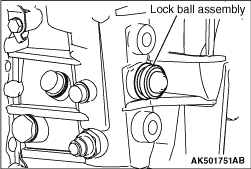
5.Remove the lock ball assembly.
|
|
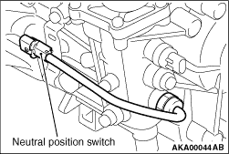
6.Remove the neutral position switch.
|
|
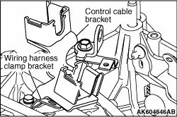
7.Remove the control cable bracket and wiring harness clamp bracket.
|
|
8.Remove the Transmission case hanger No.1.
|
|
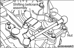
9.Remove the Shifting bellcrank assembly.
|
|
10.Remove the wiring harness clamp bracket.
|
|
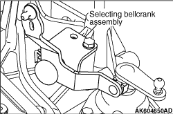
11.Remove the selecting bellcrank assembly.
|
|
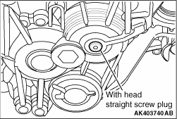
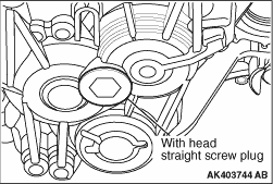
12.Remove the with head straight screw plug.
|
|
13.Remove the with head straight screw plug.
|
|
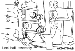
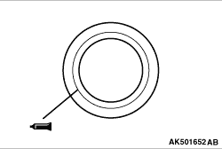
14.Remove the lock ball assembly.
|
|
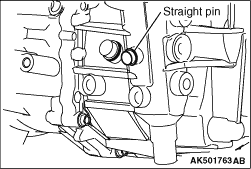
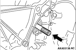
15.Remove the straight pin.
|
|
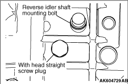
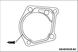
16.Remove the with head straight screw plug and gasket.
17.Remove the reverse idler shaft mounting bolt and gasket.
|
|
18.Remove the Wiring harness clamp bracket.
|
|
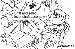
19.Remove the shift and select lever shaft assembly.
|
|
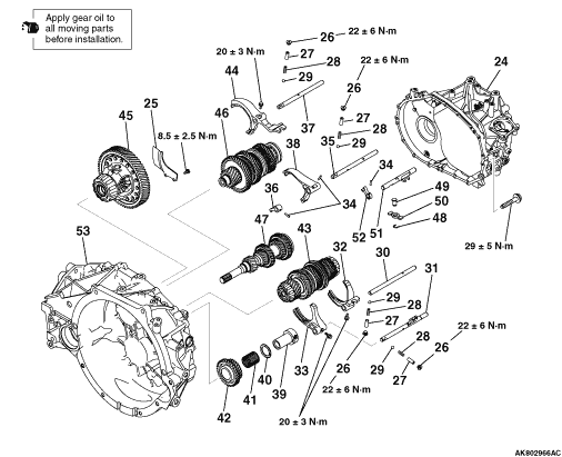
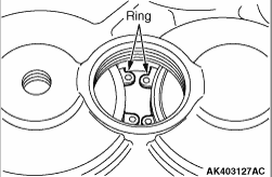
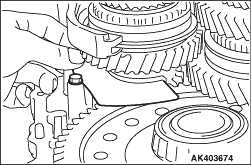
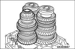
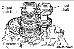
20.Use snap ring pliers to expand the indicated hole snap rings. The hole snap rings will
release the radial ball bearings, and the input shaft and output shaft No.1 will fall under
its own weight.
|
|
21.Remove the transmission case sub-assembly.
|
|
22.Remove the oil separator.
|
|
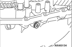
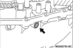
23.Remove the straight screw plug, the shift detente ball spring seat No.1, the compression
spring and ball (four places).
|
|
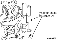
24.Remove the washer based hexagon bolt.
|
|
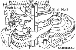
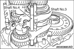
25.Remove the gear shift fork shaft No.4 and the gear shift fork shaft No.3.
|
|
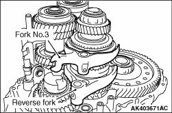
26.Remove the gear shift fork assembly No.3 and the reverse shift fork.
|
|
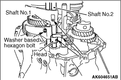
27.After removing washer based hexagon bolt the gear shift fork shaft No.1, remove the slotted
spring pin of the gear shift fork shaft No.2 and gear shift head No.2.
28.Remove the gear shift fork shaft No.2.
29.Remove the gear shift head No.2.
|
|
30.Remove the gear shift fork assembly No.2.
|
|
31.Remove the reverse idler gear shaft, reverse idler thrust washer, needle roller bearing
and reverse idler gear.
|
|
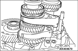
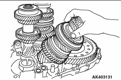
32.Remove the output shaft No.2 sub-assembly.
|
|
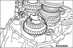
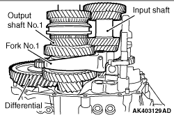
33.Remove the input shaft sub-assembly, output shaft No.1 sub-assembly and gear shift fork
assembly No.1.
34.Remove the differential sub-assembly.
|
|
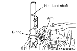
35.Remove the E-ring.
36.Remove the shift arm pivot.
37.Remove the gear shift head No.3 and gear shift fork shaft No.5 and shift arm simultaneously.
|
|
|
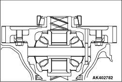
1.Set the differential assembly to the transmission case.
|
|
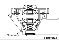
2.Push and fit the tapered roller bearing outer race by hand.
|
|
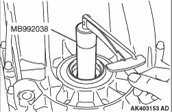
3.To fit the tapered roller bearing outer race, rotate the differential assembly by hand
about 10 times with the special tool Preload socket (MB992038).
|
|
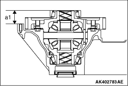
4.Put the transmission case on the surface table and use a height gauge to measure the dimension
"a1," which is from the mating surface of the transmission case to the end surface of the tapered
roller bearing outer race.
|
|
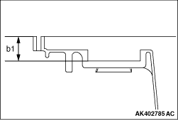
5.Put the straight edge on the mating surface of the transmission case and measure the dimension
"b1" with a vernier caliper.
6.Select the shim whose dimension is the difference between "b1" and "a1."
7.Install the differential assembly to the transmission case. Tighten the transmission
case bolts to the specified torque of 29 ±
5 N·m.
|
|
8.Using special tool Preload socket (MB992038), measure the rotational starting torque of
differential case. When it is not within the standard range, reselect the shim.
Standard value: 1.00 -
2.49 N·m
|
|
|
1.Set the output shaft No.2 assembly and differential assembly to the transmission case.
|
|
2.Push and fit the tapered roller bearing outer race by hand.
|
|
3.To fit the tapered roller bearing outer race, rotate the output shaft No.2 assembly by
hand about 10 times with the special tool Preload socket (MB992038).
|
|
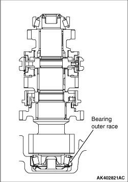
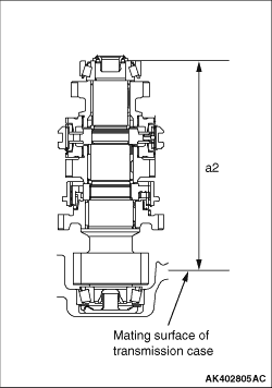
4.Put the transmission case on the surface table and measure the dimension "a2," which is
from the mating surface of the transmission case to the end surface of the bearing outer race,
with a height gauge.
|
|
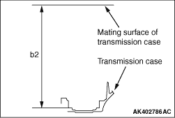
5.Put the straight edge on the mating surface of the transmission case and measure the dimension
"b2" with a vernier caliper.
6.Select the shim whose dimension is the difference between "b2" and "a2."
7.Install the output shaft No.2 assembly and differential assembly to the transmission
case. Tighten the transmission case bolts to the specified torque of 29 ±
5 N·m.
|

|
8.Using special tool Preload socket (MB992038), measure the rotational starting torque on
the differential shaft. From this rotational starting torque, subtract the value measured in
the adjustment of the bearing preload on the differential side. When this is not within the
standard range, reselect the shim.
Standard value: 4.14 -
5.87 N·m
|
|
1.Install the differential sub-assembly in the transmission case.
2.Install the input shaft sub-assembly and output shaft No.1 sub-assembly in the transmission
case simultaneously.
|
|
3.Install the output shaft No.2 sub-assembly in the transmission case as shown in the illustration.
|

|
4.Set the reverse idler gear, the needle roller bearing, the reverse idler thrust washer
and the reverse idle gear shaft.
| note |
Fit the projection of the anti-rotation for the reverse idler thrust washer into the reverse
idle gear shaft as shown.
|
5.Install them to the transmission case.
|
|
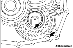
6.Before installing the transmission case assembly, confirm that the reverse idler gear
addition mark is positioned as show in the illustration.
|
|
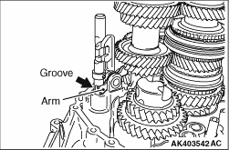
7.Insert the shift arm simultaneously into the transmission case, fitting it in the groove
of the gear shift fork shaft No.5.
|
|
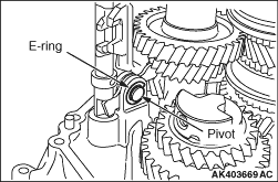
8.After insert the shift arm pivot into the transmission case and the shift arm simultaneously,
install the E-ring into the shift arm pivot.
|
|
9.Install the gear shift fork assembly No.1.
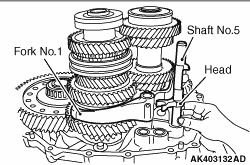
10.Install the gear shift fork shaft No.5 in the transmission case and then install the
gear shift head No.3 on the gear shift fork shaft No.5 by hammering in the slotted spring pin.
|
|
11.Install the gear shift fork assembly No.2.
|
|
12.Insert the gear shift fork shaft No.1 in the order of gear shift fork assembly No.2,
gear shift fork assembly No.1 and the transmission case.
13.Insert the shaft No.2 in the order of gear shift fork assembly No.2, gear shift head
No.2 with the shift arm and transmission case.
14.Stick the slotted spring pin in the gear shift head No.2, gear shift head No.3 and
gear shift fork assembly No.2.
15.Tighten the washer based hexagon bolts to the specified torque of 20 ±
3
N·m.
|
|
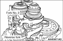
16.Install the reverse shift fork and the gear shift fork assembly No.3.
|
|
17.Insert the gear shift fork shaft No.3 in the order of gear shift fork assembly No.3, reverse
shift fork, and transmission case.
18.Insert the gear shift fork shaft No.4 in the order of reverse shift fork and transmission
case.
|
|
19.Tighten the washer based hexagon bolts to the specified torque of 20 ±
3 N·m.
|
|
20.
| caution |
As shown in the illustration, install the white painted spring only for the
reverse fork.
|
Install the ball, the compression spring, the shift detente ball spring seat No.1 and
tighten the straight screw plug (four places) to the specified torque of 22 ±
6 N·m.
|
|
21.Install the oil separator to the transmission case and tighten the bolts to the specified
torque of 8.5 ±
2.5 N·m.
|
|
22.Completely degrease the FIPG-applied surface so that water and oil including the old sealant
cannot adhere to the surface coated with the sealant.
Never touch the degreased surface by hand.
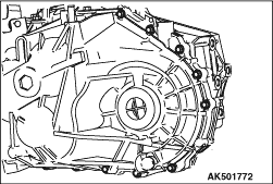
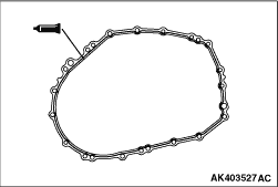
23.Apply a 1.2 mm diameter bead of form-in-place gasket (FIPG) to the transmission case
along its circumference as shown in the drawing.
Specified sealant:
MITSUBISHI MOTORS GENUINE Part No. MD997740 or equivalent
|
|
24.Install the transmission case sub-assembly and tighten the bolts to the specified torque
of 29 ±
5 N·m.
|
|
25.Extend the hole snap ring and install it on the radial ball bearing.
|
|
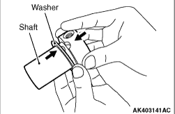
26.Install stud bolt to the output shaft No.2 sub-assembly.
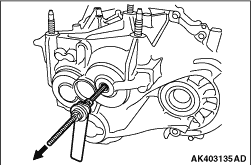
27.Pull the output shaft No.2 sub-assembly in the direction as shown in the illustration
and fit the hole snap ring into the bearing groove.
| note |
After installation, keep the sealed area away from oil for approximately one hour.
|
|
|
28.Push the input shaft sub-assembly in the direction as shown in the illustration and fit
the hole snap ring into the bearing groove.
|

|
29.Lift the output No.1 sub-assembly.
30.Confirm that the dimension between the centres of Φ
2.5 mm holes on the hole
snap ring is in accordance with the illustration.
31.Check the hole snap ring fits securely into the bearing groove.
|
|
32.Completely degrease the FIPG-applied surface so that water and oil including the old sealant
cannot adhere to the surface coated with the sealant.
Never touch the degreased surface by hand.
33.Apply a 1.2 mm diameter bead of form-in-place gasket (FIPG) to the control shaft cover
along its circumference as shown in the drawing.
Specified sealant:
MITSUBISHI MOTORS GENUINE Part No. MD997740 or equivalent
|
|
34.Install the shift and select lever shaft assembly to the transmission case and tighten
the bolts to the specified torque of 18 ±
3 N·m.
|
|
35.Install the wiring harness clamp bracket specified torque of 21 ±
1 N·m.
|
|
36.Install the reverse idler shaft mounting bolt and new gasket, and then tighten the bolt
to the specified torque of 80 ±
10 N·m.
37.Install the with head straight screw plug and gasket and then tighten the bolt to
the specified torque of 39 ±
11 N·m.
|
|
38.Install the straight pin to the specified torque of 30 ±
9 N·m.
|
|
39.Install the lock ball assembly and tighten to the specified torque of 29 ±
8
N·m.
|
|
40.Completely degrease the FIPG-applied surface so that water and oil including the old sealant
cannot adhere to the surface coated with the sealant.
Never touch the degreased surface by hand.
41.Apply a 1.2 mm diameter bead of form-in-place gasket (FIPG) to the straight screw
plug along its circumference as shown in the drawing.
Specified sealant:
MITSUBISHI MOTORS GENUINE Part No. MD997740 or equivalent
|
|
42.Install the with head straight screw plug and tighten to the specified torque of 55 N·m.
|
|
43.Install the with head straight screw plug and tighten to the specified torque of 22.4
N·m.
|
|
44.stall the selecting bellcrank assembly specified toque of 18 ±
3 N·m.
|
|
45.Install the wiring harness clamp bracket to selecting bellcrank assembly specified toque
of 19 ±
3 N·m
|
|
46.Install the shifting bellcrank assembly specified toque of 18 ±
3 N·m.
47.Install the nut specified toque of 11 ±
2 N·m.
|
|
48.Install the Transmission case hanger No.1 specified toque of 18 ±
3 N·m.
|
|
49.50.Install the whirring harness clamp bracket to the transmission case and tighten the
bolts to the specified torque of 20 ±
8 N·m.
|
|
51.Install the neutral position switch and tighten to the specified torque of 34 ±
5
N·m.
|
|
52.Install the lock ball assembly and tighten to the specified torque of 39 ±
11
N·m.
|
|
53.Install the back-up lamp switch assembly and tighten to the specified torque of 40 ±
11
N·m.
54.Install the roll stopper bracket and tighten to the specified torque of 90 ±
10
N·m.
55.Install the transfer and tighten to the specified torque of 69 ±
9 N·m.
|