
|
1.Using special tool Bearing remover (MD998801), support the ball bearing, and then set
them on the press.
2.Push down on the input shaft with the press and remove the ball bearing.
|

|
1.Using special tool Bearing remover (MD998917), support the 5th speed gear, and then set
them on the press.
2.Push down on the input shaft with the press and remove the 5th speed-reverse synchronizer
hub.
|

|
1.Using special tool Bearing remover (MD998801), support the 4th speed gear, and then set
them on the press.
2.Push down on the input shaft with the press and remove the 5th speed gear sleeve.
|

|
1.Using special tool Bearing remover (MD998801), support the 3rd speed gear, and then set
them on the press.
2.Push down on the input shaft with the press and remove the 4th speed gear sleeve.
|

|
1.Using special tool Bearing remover (MD998801), support the ball bearing, and then set
them on the press.
2.Push down on the input shaft with the press and remove the ball bearing.
|

|
Install the oil seal into the end of the input shaft as shown.
|

|
1.Using special tool Bearing remover (MD998801), support the 2nd speed gear portion of the
input shaft, and then set them on the press.
2.Using special tools, press install the ball bearing with the press.
- Installer cap (MD998812)
- Installer-100 (MD998813)
- Installer adapter (MD998816)
|

|
1.Install the thickest snap ring that can be fitted in the snap ring groove of input shaft.
2.Make sure that the front bearing axial play meets the standard value.
Standard value: 0 -
0.12 mm
|

|
Install the synchronizer spring onto the synchronizer ring as shown.
|

|
1.Ascertain whether or not there are identification notches on the synchronizer ring.
Two notches: 3rd speed synchronizer ring
No notches: 4th speed synchronizer ring
2.Install the synchronizer ring so that it completely fits over the machined cone of
the gear.
|

|
1.Using special tool Bearing remover (MD998801), support the 2nd speed gear portion of the
input shaft, and then set them on the press.
2.Make sure that the synchronizer ring has been perfectly matched to the 3rd speed gear
cone.
3.Check the installation direction of the 3rd-4th speed synchronizer hub, and put it
on the input shaft.
|

|
4.Using special tools, press install the 3rd-4th speed synchronizer hub with the press.
- Installer cap (MD998812)
- Installer-100 (MD998813)
- Installer adapter (MD998825)
5.Make sure that the synchronizer ring can rotate freely.
|

|
1.Check the installation direction of the synchronizer sleeve, and install it onto the 3rd-4th
speed synchronizer hub.
|

|
2.Install the synchronizer sleeve so that the areas with teeth that have raised tips (three
areas total) are aligned with the areas on the synchronizer hub that have deep grooves between
the teeth (three areas total).
|

|
1.Using special tool Bearing remover (MD998801), support the 2nd speed gear portion of the
input shaft, and then set them on the press.
2.Using special tools, install the 4th speed gear sleeve with the press.
- Installer cap (MD998812)
- Installer-100 (MD998813)
- Installer adapter (MD998824)
|
|
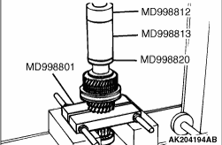
1.Using special tool Bearing remover (MD998801), support the 2nd speed gear portion of the
input shaft, and then set them on the press.
2.Using special tools, install the 5th speed gear sleeve onto the input shaft with the
press.
- Installer cap (MD998812)
- Installer-100 (MD998813)
- Installer adapter (MD998820)
|

|
1.Check that the 5th speed- reverse synchronizer hub is in the correct installation direction,
and put it on the input shaft.
|

|
2.Using special tool Bearing remover (MD998801), support the input shaft gear, and then
set them on the press.
3.Using special tools, install the 5th speed-reverse synchronizer hub with the press.
- Installer cap (MD998812)
- Installer adapter (MD998819)
4.Make sure that the synchronizer ring on the 5th speed gear side can rotate freely.
|

|
1.Install the synchronizer sleeve so that the identification grooves are oriented in the
direction shown.
|
|
2.When the synchronizer sleeve is installed, check that the deep groove portion of the synchronizer
hub is aligned with the projecting portion of the sleeve.
|

|
1.Using special tool Bearing remover (MD998801), support the 2nd speed gear portion of the
input shaft, and then set them on the press.
2.Using special tools, install the ball bearing onto the input shaft with the press.
- Installer cap (MD998812)
- Installer adapter (MD998818)
|
|
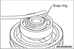
1.Install the thickest snap ring that can be fitted in the groove of the input shaft.
2.Make sure that the rear bearing axial play meets the standard value.
Standard value:
|

