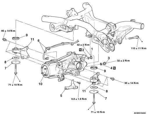
REMOVAL AND INSTALLATION


caution
  • The parts indicated by * are the bolts with friction coefficient stabilizer. In removal, ensure there is no damage, clean dust and soiling from the bearing and thread surfaces, and tighten them to the specified torque.

Pre-removal operation
  • Differential Gear Oil Draining (Refer to ).
  • Propeller Shaft Assembly Removal (Refer to GROUP25 -Propeller Shaft ).
  • Rear Driveshaft Assembly Removal (Refer to ).

Post-installation operation
  • Rear Driveshaft Assembly Installation (Refer to ).
  • Propeller Shaft Assembly Installation (Refer to GROUP25-Propeller Shaft ).
  • Differential Gear Oil Filling (Refer to ).


Removal steps


1.
Filler plug


2.
Gasket


3.
Drain plug


4.
Gasket


5.
Cover


6.
Electronic control coupling harness connection, breather hose connection


7.
Weight


8.
Lower stopper


9.
Upper stopper

>>A<<
10.
Differential carrier assembly


11.
Differential mount bracket (LH/RH)

INSTALLATION SERVICE POINTS


For installation service points, follow the same service procedures as 10 MY OUTLANDER.