REMOVAL AND INSTALLATION


caution
  • Disconnect the battery (-) terminal and wait for 60 seconds or more before starting work. Insulate the disconnected (-) terminal by wrapping a tape.
  • Handle the front impact sensor with sufficient caution, and do not drop the sensor or allow contact with water, oil, or others. If a dent, crack, deformation and others are discovered, replace it with a new one.


Headlamp support upper panel removal steps


·
Front bumper assembly removal and installation (Refer to GROUP 51 - Front Bumper Assembly .)


1.
Front bumper cover


·
Hood latch switch harness and front harness connection


2.
Hood lock release cable


3.
Hood latch


4.
Radiator cap assembly bracket and radiator upper hose <4B1>


5.
Air cleaner intake duct


·
Horn (HI), horn (LO) (Refer to GROUP 54A - Horn .)


·
Front impact sensor (Refer to GROUP 52B - Front impact sensor .)

>>A<<
6.
Headlamp support upper panel


Front fender garnish removal


7.
Front fender garnish <Diesel-powered vehicles>


Front end crossmember dynamic damper removal


8.
Front end crossmember dynamic damper <Some models>


Air guide side panel removal


9.
Air guide side panel <Some models>


Front floor backbone brace removal


10.
Front floor backbone brace <Diesel-powered vehicles>


Dash panel heat protector removal


11.
Dash panel heat protector


Rear seat crossmember removal


12.
Rear seat crossmember


Tie down hook rear removal


13.
Tie down hook rear


Rear end brace removal


14.
Rear end brace


Rear wheelhouse brace removal


15.
Rear wheelhouse brace

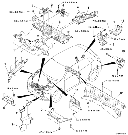
INSTALLATION SERVICE POINT


>>A<< HEADLAMP SUPPORT UPPER PANEL INSTALLATION


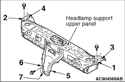
Tighten the headlamp support upper pane mounting bolts in the numerical order to 9.0 ± 2.0 N·m.