|
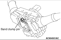
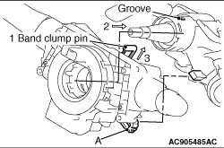
1.Using a wrench or similar tool, pinch and lift the band clump pin shown in the figure.
|
|
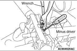
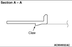
2.With the flat-tipped screwdriver inserted into the column shaft groove shown in the figure,
lift the claw shown in Section A-A, and then remove the column switch body by pulling out the
switch body.
|
|
1.Using a wrench or similar tool, pinch and lift the band clump pin shown in the figure.
2.Align the part "A" position in the figure with the steering lock side rib, and then
insert the switch body into the column shaft.
3.After mounting the column switch body by securely fitting the column switch body claw
with the column shaft groove, release the band clump pin.
|