CAN BUS DIAGNOSTICS TABLE
| caution |
|
| M.U.T.-III screen |
Diagnosis detail |
Reference page |
|
| (The ECUs that are not adopted are not displayed). |
Comment |
||
 |
Trouble is suspected in the section displayed in red. |
Diagnosis Item 1 Diagnose when the M.U.T.-III cannot receive the data sent by ETACS-ECU |
 |
 |
Trouble is suspected in the section displayed in red. |
Diagnosis Item 2 Malfunction of the ETACS-ECU |
|
 |
CAN-C: A bus-off failure is present in the gateway ECU. |
Diagnosis Item 3 Abnormal short between the CAN-C bus lines |
|
| CAN-C: Earthing in red displayed area is estimated |
Diagnosis Item 4 Diagnose shorts in the earth to CAN-C bus line |
|
|
| CAN-C: Short circuit to battery in red displayed area is estimated |
Diagnosis Item 5 Diagnose shorts in the power supply to CAN-C bus line |
|
|
 |
CAN-C: Disconnection in red displayed area is estimated. |
Diagnosis Item 6 Diagnose when the M.U.T.-III cannot receive the data sent by steering wheel sensor <vehicles with ASC or headlamp automatic levelling system> |
|
 |
CAN-C: Disconnection in red displayed area is estimated. |
Diagnosis Item 7 Diagnose when the M.U.T.-III cannot receive the data sent by 4WD-ECU <4WD> |
|
 |
CAN-C: Disconnection in red displayed area is estimated. |
Diagnosis Item 8 Diagnose when the M.U.T.-III cannot receive the data sent by corner sensor/back sensor-ECU <vehicles with reversing sensor system> |
|
 |
CAN-C: Disconnection in red displayed area is estimated. |
Diagnosis Item 9 Diagnose when the M.U.T.-III cannot receive the data sent by CVT-ECU <CVT> |
|
 |
CAN-C: Disconnection in red displayed area is estimated. |
Diagnosis Item 10 Diagnose when the M.U.T.-III cannot receive the data sent by ABS-ECU <vehicles without ASC> or ASC-ECU <vehicles with ASC> |
|
 |
CAN-C: Disconnection in red displayed area is estimated. |
Diagnosis Item 11 Diagnose when the M.U.T.-III cannot receive the data sent by headlamp automatic levelling-ECU <vehicles with headlamp automatic levelling system> |
|
 |
CAN-C: Disconnection in red displayed area is estimated. |
Diagnosis Item 12 Diagnose when the M.U.T.-III cannot receive the data sent by EPS-ECU |
|
 |
CAN-C: Disconnection in red displayed area is estimated. |
Diagnosis Item 13 Diagnose when the M.U.T.-III cannot receive the data sent by AS&G-ECU <vehicles with automatic stop & go system> |
|
 |
CAN-C: Disconnection in red displayed area is estimated. |
Diagnosis Item 14 Diagnose when the M.U.T.-III cannot receive the data sent by engine-ECU |
|
|
CAN-C: Disconnection in red displayed area is estimated. |
Diagnosis Item 15 Diagnose the lines between the ETACS-ECU and joint connector (CAN2) |
|
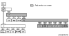 |
CAN-C: Disconnection in red displayed area is estimated. |
Diagnosis Item 16 Diagnose the lines between joint connector (CAN2) and joint connector (CAN3) |
|
 |
CAN-B: Disconnection in red displayed area is estimated. |
Diagnosis Item 17 Diagnose when the M.U.T.-III cannot receive the data sent by KOS-ECU <vehicles with KOS> |
|
| Diagnosis Item 18 Diagnose when the M.U.T.-III cannot receive the data sent by WCM <vehicles without KOS> |
|
||
 |
CAN-B: Disconnection in red displayed area is estimated. |
Diagnosis Item 19 Diagnose when the M.U.T.-III cannot receive the data sent by SRS-ECU |
|
 |
CAN-B: Disconnection in red displayed area is estimated. |
Diagnosis Item 20 Diagnose when the M.U.T.-III cannot receive the data sent by heater control panel <vehicles without A/C> or A/C control panel <vehicles with A/C> |
|
 |
CAN-B: Disconnection in red displayed area is estimated. |
Diagnosis Item 21 Diagnose when the M.U.T.-III cannot receive the data sent by combination meter |
|
 |
CAN-B: Disconnection in red displayed area is estimated. |
Diagnosis Item 22 Diagnose when the M.U.T.-III cannot receive the data sent by OSS-ECU <vehicles with KOS> |
|
 |
CAN-B: A failure in the red section, or a bus-off failure is present
in the gateway ECU. |
Diagnosis Item 23 Short to power supply or earth in both CAN_H and CAN_L lines of the CAN-B bus lines. |
|
 |
CAN-B: Disconnection in red displayed area is estimated. |
Diagnosis Item 24 Diagnose the ETACS-ECU, joint connector (CAN1) or lines between ETACS-ECU and joint connector (CAN1) |
|
|
CAN-B: Disconnection in red displayed area is estimated. |
Diagnosis Item 25 Short to power supply or earth, open circuit or line-to-line short in the CAN-B bus lines |
|