Diagnosis Item
3: Abnormal short between the CAN-C bus lines
| caution |
When servicing a CAN bus line,
earth yourself by touching a metal object such as an unpainted water pipe. If you fail to do,
a component connected to the CAN bus line may be broken.
|
FUNCTION
TROUBLE JUDGEMENT CONDITIONS
TROUBLESHOOTING HINTS
- Malfunction of the connector (joint connectors or ECU connectors improperly
connected)
- Malfunction of the wiring harness (line-to-line short in the CAN-C main or sub bus
lines)
- Malfunction of the ECU (ECU on CAN-C lines failed)
|
|
STEP 1. Connector check: C-202 joint connector (CAN2) and
C-24 joint connector (CAN3)
|
|
|
| caution |
The strand end of the twist wire should be within 10 cm from
the connector. For details refer to  . .
|
|
|
|
Q.
Is the check result normal?
|
|
|
YES <4WD> : Go to Step 2. : Go to Step 2.
|
|
|
|
|
|
YES <2WD (Vehicles with ASC or headlamp automatic levelling system> : Go to Step 3.
|
|
|
|
|
|
YES <2WD (Vehicles with reversing sensor system and Vehicles without ASC and
headlamp automatic levelling system> : Go to Step 4.
|
|
|
|
|
|
YES <Vehicles without ASC, headlamp automatic levelling system and reversing
sensor system> : Go to Step 5.
|
|
|
|
|
|
NO : Repair the defective connector.
|
|
|
|
|
|
STEP 2. Check the wiring harness between C-228 4WD-ECU and C-202 joint
connector (CAN2) for line-to-line short.
|
|
|
| caution |
- A digital multimeter should be used. For details
refer to .
- The test wiring harness should be used. For details refer to .
|
|
|
|
(1)Disconnect joint connector (CAN2), and check that there is continuity at the harness
side.
|
|
|
(2)Check that there is continuity between C-202 joint connector terminal No.8 and
19.
OK: 1 kΩ or more
|
|
|
Q.
Is the check result normal?
|
|
|
 Go to Step 3. Go to Step 3.
|
|
|
|
|
|
 Go to Step 12. Go to Step 12.
|
|
|
|
|
|
STEP 3. Check the wiring harness between C-310 steering wheel sensor
connector and C-202 joint connector (CAN2) for line-to-line short.
|
|
|
| caution |
- A digital multimeter should be used. For details
refer to .
- The test wiring harness should be used. For details refer to .
|
|
|
|
(1)Disconnect joint connector (CAN2), and check that there is continuity at the harness
side.
|
|
|
(2)Check that there is continuity between C-202 joint connector terminal No.9 and
20.
OK: 1 kΩ or more
|
|
|
Q.
Is the check result normal?
|
|
|
YES <Vehicles with reversing sensor system> : Go to Step 4.
|
|
|
|
|
|
YES <Vehicles without reversing sensor system> : Go to Step 5.
|
|
|
|
|
|
Go to Step 13.
|
|
|
|
|
|
STEP 4. Check the wiring harness between C-13 corner sensor/back sensor-ECU
connector and C-202 joint connector (CAN2) for line-to-line short.
|
|
|
| caution |
- A digital multimeter should be used. For details
refer to .
- The test wiring harness should be used. For details refer to .
|
|
|
|
(1)Disconnect joint connector (CAN2), and check that there is continuity at the harness
side.
|
|
|
(2)Check that there is continuity between C-202 joint connector terminal No.7 and
18.
OK: 1 kΩ or more
|
|
|
Q.
Is the check result normal?
|
|
|
Go to Step 5.
|
|
|
|
|
|
Go to Step 14.
|
|
|
|
|
|
STEP 5. Check the wiring harness between B-10 <diesel> or
B-27 <petrol> engine-ECU connector and C-24 joint connector (CAN3) for line-to-line
short.
|
|
|
| caution |
- A digital multimeter should be used.
- The test wiring harness should be used.
|
|
|
|
(1)Disconnect joint connector (CAN3), and check that there is continuity at the harness
side.
|
|
|
(2)Check that there is continuity between C-24 joint connector terminal Nos.7 and
18.
OK: 120 ± 20 Ω
|
|
|
Q.
Is the check result normal?
|
|
|
YES <CVT> : Go to Step 6.
|
|
|
|
|
|
YES <M/T (Vehicles with automatic stop & go system)> : Go to Step 7.
|
|
|
|
|
|
YES <M/T (Vehicles without automatic stop & go system)> : Go to Step 8.
|
|
|
|
|
|
NO : Go to Step 15.
|
|
|
|
|
|
STEP 6. Check the wiring harness between C-131 CVT-ECU connector and
C-24 joint connector (CAN3) for line-to-line short.
|
|
|
| caution |
- A digital multimeter should be used. For details
refer to .
- The test wiring harness should be used. For details refer to .
|
|
|
|
(1)Disconnect joint connector (CAN3), and check that there is continuity at the harness
side.
|
|
|
(2)Check that there is continuity between C-24 joint connector terminal No.5 and 16.
OK: 1 kΩ or more
|
|
|
Q.
Is the check result normal?
|
|
|
Go to Step 8.
|
|
|
|
|
|
Go to Step 16.
|
|
|
|
|
|
STEP 7. Check the wiring harness between C-11 AS&G-ECU connector
and C-24 joint connector (CAN3) for line-to-line short.
|
|
|
| caution |
- A digital multimeter should be used. For details
refer to .
- The test wiring harness should be used. For details refer to .
|
|
|
|
(1)Disconnect joint connector (CAN3), and check that there is continuity at the harness
side.
|
|
|
(2)Check that there is continuity between C-24 joint connector terminal No.6 and 17.
OK: 1 kΩ or more
|
|
|
Q.
Is the check result normal?
|
|
|
Go to Step 8.
|
|
|
|
|
|
Go to Step 17.
|
|
|
|
|
|
STEP 8. Check the wiring harness between C-221 EPS-ECU connector and
C-24 joint connector (CAN3) for line-to-line short.
|
|
|
| caution |
- A digital multimeter should be used. For details
refer to .
- The test wiring harness should be used. For details refer to .
|
|
|
|
(1)Disconnect joint connector (CAN3), and check that there is continuity at the harness
side.
|
|
|
(2)Check that there is continuity between C-24 joint connector terminal No.9 and 20.
OK: 1 kΩ or more
|
|
|
Q.
Is the check result normal?
|
|
|
YES <Vehicles with headlamp automatic levelling system> : Go to Step 9.
|
|
|
|
|
|
YES <Vehicles without headlamp automatic levelling system> : Go to Step 10.
|
|
|
|
|
|
NO : Go to Step 18.
|
|
|
|
|
|
STEP 9. Check the wiring harness between C-117 headlamp automatic
levelling-ECU connector and C-24 joint connector (CAN3) for line-to-line short.
|
|
|
| caution |
- A digital multimeter should be used. For details
refer to .
- The test wiring harness should be used. For details refer to .
|
|
|
|
(1)Disconnect joint connector (CAN2), and check that there is continuity at the harness
side.
|
|
|
(2)Check that there is continuity between C-24 joint connector terminal No.10 and
21.
OK: 1 kΩ or more
|
|
|
Q.
Is the check result normal?
|
|
|
Go to Step 10.
|
|
|
|
|
|
Go to Step 19.
|
|
|
|
|
|
STEP 10. Check the wiring harness between A-67 ABS-ECU <Vehicles
without ASC> or A-03 ASC-ECU <Vehicles with ASC> connector and C-24
joint connector (CAN3) for line-to-line short.
|
|
|
| caution |
- A digital multimeter should be used. For details
refer to .
- The test wiring harness should be used. For details refer to .
|
|
|
|
(1)Disconnect joint connector (CAN3), and check that there is continuity at the harness
side.
|
|
|
(2)Check that there is continuity between C-24 joint connector terminal No.8 and 19.
OK: 1 kΩ or more
|
|
|
Q.
Is the check result normal?
|
|
|
Go to Step 11.
|
|
|
|
|
|
Go to Step 20.
|
|
|
|
|
|
STEP 11. Check the wiring harness between C-411 ETACS-ECU connector
and C-202 joint connector (CAN2) for line-to-line short.
|
|
|
| caution |
- A digital multimeter should be used.
- The test wiring harness should be used.
- Strictly observe the specified wiring harness repair procedure.
|
|
|
|
(1)Disconnect joint connector (CAN2), and check that there is continuity at the harness
side.
|
|
|
(2)Check that there is continuity between C-202 joint connector terminal 11 and 22.
OK: 120 ± 20 Ω
|
|
|
Q.
Is the check result normal?
|
|
|
Check C-128 intermediate connector, and repair if necessary. If the intermediate
connector is in good condition, repair the wiring harness between C-202 joint connector (CAN2)
and C-24 joint connector (CAN3).
|
|
|
|
|
|
Go to Step 21.
|
|
|
|
|
|
STEP 12. M.U.T.-III CAN bus diagnostics (checking the 4WD-ECU for
internal short)
|
|
|
| caution |
Strictly observe the specified wiring harness repair procedure.
|
|
|
|
Disconnect C-228 4WD-ECU connector, and diagnose the CAN bus line.
|
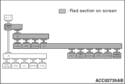
|
OK: The display of the M.U.T.-III is as shown in the figure.
Q.
Does M.U.T.-III screen correspond to the illustration?
Check C-27 intermediate connectors, and repair if necessary. If the intermediate
connector is in good condition, repair the wiring harness between C-228 4WD-ECU connector and
C-202 joint connector (CAN2).
Check the 4WD-ECU connector, and repair if necessary. If the 4WD-ECU connector
is in good condition, replace the 4WD-ECU.
|
|
|
STEP 13. M.U.T.-III CAN bus diagnostics (checking the steering wheel
sensor for internal short)
|
|
|
| caution |
Strictly observe the specified wiring harness repair procedure.
|
|
|
|
Disconnect C-310 steering wheel sensor connector, and diagnose the CAN bus line.
|
|
OK: The display of the M.U.T.-III is as shown in the figure.
Q.
Does M.U.T.-III screen correspond to the illustration?
Repair the wiring harness between C-310 steering wheel sensor connector and C-202
joint connector (CAN2).
Check the steering wheel sensor connector, and repair if necessary. If the steering
wheel sensor connector is in good condition, replace the steering wheel sensor.
|
|
|
STEP 14. M.U.T.-III CAN bus diagnostics (checking the corner sensor/back
sensor-ECU for internal short)
|
|
|
| caution |
Strictly observe the specified wiring harness repair procedure.
|
|
|
|
Disconnect C-13 corner sensor/back sensor-ECU connector, and diagnose the CAN bus line.
|
|
OK: The display of the M.U.T.-III is as shown in the figure.
Q.
Does M.U.T.-III screen correspond to the illustration?
Repair the wiring harness between C-13 corner sensor/back sensor-ECU connector
and C-202 joint connector (CAN2).
Check the corner sensor/back sensor-ECU connector, and repair if necessary. If
the corner sensor/back sensor-ECU connector is in good condition, replace the corner sensor/back
sensor-ECU.
|
|
|
STEP 15. M.U.T.-III CAN bus diagnostics (checking the engine-ECU for
internal short)
|
|
|
| caution |
Strictly observe the specified wiring harness repair procedure.
|
|
|
|
Disconnect B-10 <diesel> or B-27 <petrol> engine-ECU connector,
and diagnose the CAN bus line.
|
|
OK: The display of the M.U.T.-III is as shown in the figure.
Q.
Does M.U.T.-III screen correspond to the illustration?
Repair the wiring harness between B-10 <diesel> or B-27 <petrol> engine-ECU
connector and C-24 joint connector (CAN3).
Check the engine-ECU connector, and repair if necessary. If the engine-ECU connector
is in good condition, replace the engine-ECU.
|
|
|
STEP 16. M.U.T.-III CAN bus diagnostics (checking the CVT-ECU for
internal short)
|
|
|
| caution |
Strictly observe the specified wiring harness repair procedure.
|
|
|
|
Disconnect C-131 CVT-ECU connector, and diagnose the CAN bus line.
|
|
OK: The display of the M.U.T.-III is as shown in the figure.
Q.
Does M.U.T.-III screen correspond to the illustration?
Repair the wiring harness between C-131 CVT-ECU connector and C-24 joint connector
(CAN3).
Check the CVT-ECU connector, and repair if necessary. If the CVT-ECU connector
is in good condition, replace the CVT-ECU.
|
|
|
STEP 17. M.U.T.-III CAN bus diagnostics (checking the AS&G-ECU
for internal short)
|
|
|
| caution |
Strictly observe the specified wiring harness repair procedure.
|
|
|
|
Disconnect C-11 AS&G-ECU connector, and diagnose the CAN bus line.
|
|
OK: The display of the M.U.T.-III is as shown in the figure.
Q.
Does M.U.T.-III screen correspond to the illustration?
Repair the wiring harness between C-11 AS&G-ECU connector and C-24 joint
connector (CAN3).
Check the AS&G-ECU connector, and repair if necessary. If the AS&G-ECU
connector is in good condition, replace the AS&G-ECU.
|
|
|
STEP 18. M.U.T.-III CAN bus diagnostics (checking the EPS-ECU for
internal short)
|
|
|
| caution |
Strictly observe the specified wiring harness repair procedure.
|
|
|
|
Disconnect C-221 EPS-ECU connector, and diagnose the CAN bus line.
|
|
OK: The display of the M.U.T.-III is as shown in the figure.
Q.
Does M.U.T.-III screen correspond to the illustration?
Repair the wiring harness between C-221 EPS-ECU connector and C-24 joint connector
(CAN3).
Check the EPS-ECU connector, and repair if necessary. If the EPS-ECU connector
is in good condition, replace the EPS-ECU.
|
|
|
STEP 19. M.U.T.-III CAN bus diagnostics (checking the headlamp automatic
levelling-ECU for internal short)
|
|
|
| caution |
Strictly observe the specified wiring harness repair procedure.
|
|
|
|
Disconnect C-117 headlamp automatic levelling-ECU connector, and diagnose the CAN bus
line.
|
|
OK: The display of the M.U.T.-III is as shown in the figure.
Q.
Does M.U.T.-III screen correspond to the illustration?
Repair the wiring harness between C-117 headlamp automatic levelling-ECU connector
and C-24 joint connector (CAN3).
Check the headlamp automatic levelling-ECU connector, and repair if necessary.
If the headlamp automatic levelling-ECU connector is in good condition, replace the headlamp
automatic levelling-ECU.
|
|
|
STEP 20. M.U.T.-III CAN bus diagnostics (checking the ABS-ECU <Vehicles
without ASC> or ASC-ECU <Vehicles with ASC> for internal short)
|
|
|
| caution |
Strictly observe the specified wiring harness repair procedure.
|
|
|
|
Disconnect A-67 ABS-ECU <Vehicles without ASC> or A-03 ASC-ECU <Vehicles
with ASC> connector, and diagnose the CAN bus line.
|
|
OK: The display of the M.U.T.-III is as shown in the figure.
Q.
Does M.U.T.-III screen correspond to the illustration?
Repair the wiring harness between A-67 ABS-ECU <Vehicles without ASC> or
A-03 ASC-ECU <Vehicles with ASC> connector and C-24 joint connector (CAN3).
Check the ABS-ECU <Vehicles without ASC> or ASC-ECU <Vehicles
with ASC> connector, and repair if necessary. If the ABS-ECU <Vehicles without
ASC> or ASC-ECU <Vehicles with ASC> connector is in good condition,
replace the ABS-ECU <Vehicles without ASC> or ASC-ECU <Vehicles with
ASC>.
|
|
|
STEP 21. Check the wiring harness between C-411 ETACS-ECU connector
and C-202 joint connector (CAN2) for line-to-line short.
|
|
|
| caution |
- A digital multimeter should be used.
- The test wiring harness should be used.
- Strictly observe the specified wiring harness repair procedure.
|
|
|
|
(1)Disconnect the ETACS-ECU connector and the joint connector (CAN2), and check that
there is continuity at the harness side.
|
|
|
(2)Check that there is continuity between C-202 joint connector terminal 11 and 22.
OK: 1 kΩ or more
|
|
|
Q.
Is the check result normal?
|
|
|
Go to Step 22.
|
|
|
|
|
|
Repair the wiring harness between C-411 ETACS-ECU connector and C-202 joint connector
(CAN2).
|
|
|
|
|
|
STEP 22. Trouble symptom check
|
|
|
Diagnose the CAN bus line, and check that normal condition is displayed.
|
|
|
Q.
Is the check result normal?
|
|
|
The trouble can be an intermittent malfunction (Refer to GROUP 00 - How
to use Troubleshooting/inspection Service Points - How to Cope with Intermittent
Malfunction).
|
|
|
|
|
|
Check the ETACS-ECU connector, and repair if necessary. If the ETACS-ECU connector
is in good condition, replace the ETACS-ECU.
|
|
|
|