REMOVAL AND INSTALLATION
| caution | When the hydraulic unit (integrated with ASC-ECU)
is replaced, after turning the ignition switch ON or OFF (vehicle information from ETACS-ECU
is registered), always carry out the calibration of all sensors (steering wheel sensor, G and
yaw rate sensor, and brake fluid pressure sensor) at one time (Refer to  , and ). , and ). |
| note | ASC-ECU is located in the hydraulic unit. |
Pre-removal Operation
|
Post-installation Operation
|
 |
|
REMOVAL SERVICE POINTS |
<<A>> ASC-ECU HARNESS CONNECTOR DISCONNECTION |
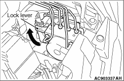 |
While pressing the fixing claw of the lock lever, operate the lock lever to
disconnect the ASC-ECU harness connector as shown. |
<<B>> HYDRAULIC UNIT (ASC-ECU) REMOVAL |
|
INSTALLATION SERVICE POINT |
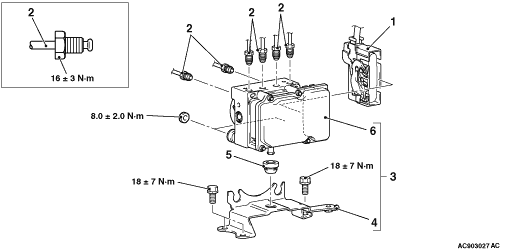
>>A<< BRAKE TUBE CONNECTION |
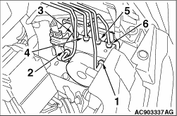 |
Install the brake tube to the hydraulic unit as shown in the figure. 1.From master cylinder (primary) 2.From master cylinder (secondary) 3.To front brake (RH) 4.To rear brake (LH) 5.To rear brake (RH) 6.To front brake (LH) |