|
|
Use the M.U.T.-III to diagnose the CAN bus lines.
|
|
|
Q.
Is the check result normal?
|
|
|
 Repair the CAN bus lines. (Refer to GROUP 54C - Troubleshooting Repair the CAN bus lines. (Refer to GROUP 54C - Troubleshooting  .)
Then, go to Step 2. .)
Then, go to Step 2.
|
|
|
|
|
|
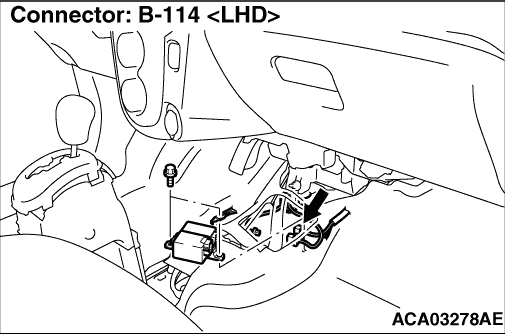
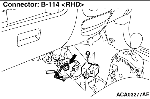
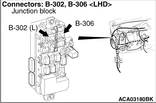
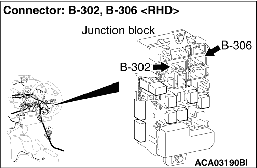
- Check the B-114 EPS-ECU connector terminal No. 2, No. 3, and junction block
connector for improper engagement, terminal damage, or drawn-in terminal to the connector case.
|
|
|
Q.
Are the connector and terminal normal?
|
|
|
Repair the damaged connector.
|
|
|
|
|
|
- Disconnect the connector and measure at the wiring harness
side.
- Turn the electric motor switch to the "ON" position.
- Measure the voltage between B-114 EPS-ECU connector terminal No. 3 and the body
earth.
|
|
|
Q.
Is the check result normal?
|
|
|
- Disconnect the connector and measure at the wiring harness
side.
- Measure the voltage between B-114 EPS-ECU connector terminal No. 2 and the body
earth.
|
|
|
Q.
Is the check result normal?
|
|
|
- Disconnect the connector and measure at the wiring harness
side.
- Measure the resistance between B-114 EPS-ECU connector terminal No. 1 and the body
earth.
|
|
|
OK: Continuity exists (2 Ω or less).
|
|
|
Q.
Is the check result normal?
|
|
|
- Check the wiring harness between B-114 EPS-ECU connector and junction block
connector for any abnormality.
|
|
|
Q.
Is the wiring harness normal?
|
|
|
Repair the wiring harness.
|
|
|
|
|
|
- Check the wiring harness between B-114 EPS-ECU connector and the fusible
link No. 23 for any abnormality.
|
|
|
Q.
Is the wiring harness normal?
|
|
|
Repair the wiring harness.
|
|
|
|
|
|
- Check the wiring harness between B-114 EPS-ECU connector
and the body earth for any abnormality.
|
|
|
Q.
Is the wiring harness normal?
|
|
|
Repair the wiring harness.
|
|
|
|
|
|
- Refer to GROUP 54A - Battery Test .
|
|
|
Q.
Is the auxiliary battery normal?
|
|
|
Charge or replace the auxiliary battery.
|
|
|
|
|
|
- Check if the diagnosis code is set to the on board charger.
|
|
|
Q.
Is the diagnosis code set?
|
|
|
 Carry out the troubleshooting on the on board charger (Refer to GROUP 54D - On
Board Charger/DC-DC Converter - Diagnosis Code Chart ). Carry out the troubleshooting on the on board charger (Refer to GROUP 54D - On
Board Charger/DC-DC Converter - Diagnosis Code Chart ).
|
|
|
|
|
|
Q.
Is the check result normal?
|
|
|
An intermittent malfunction may be present. (Refer to GROUP 00 - How
to Cope with Intermittent Malfunction ).
|
|
|
|
|
|
Replace EPS-ECU.(Refer to .)
|
|
|
|