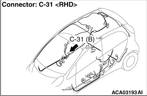
|
|
(1)Check that the negative auxiliary battery terminal is disconnected. If the negative
auxiliary battery terminal is connected, disconnect it.
|
|
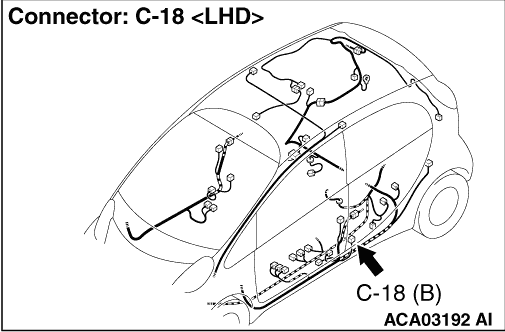
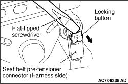
(2)Disconnect seat belt pre-tensioner (driver’s side) connector C-18 <LHD> or
C-31 <RHD>. Use a flat-tipped screwdriver to pull out the locking button at
the harness side connector, and then disconnect the connector.
|
|
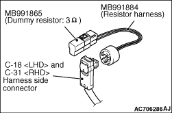
(3)Connect special tool dummy resistor (MB991865) to special tool resistor harness (MB991884).
(4)Connect special tool resistor harness to the C-18 <LHD> or C-31 <RHD>harness
side connector.
(5)Connect the negative auxiliary battery terminal.
(6)After erasing the diagnosis code memory, check the diagnosis code again.
(7)Disconnect the negative auxiliary battery terminal.
Q.
Is the diagnosis code No. B1606 set?
 Go to Step 2 Go to Step 2
 Replace the seat belt with pre-tensioner (driver’s side) (Refer to Replace the seat belt with pre-tensioner (driver’s side) (Refer to  ). ).
|
|
|
(1)Check that the negative auxiliary battery terminal is disconnected. If the negative
auxiliary battery terminal is connected, disconnect it.
|
|
|
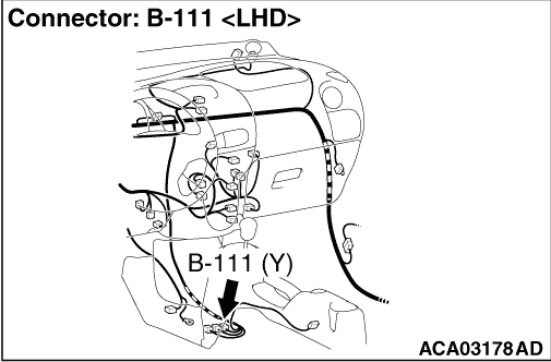
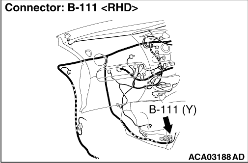
(2)Disconnect the B-111 SRS-ECU connector.
|
|
(3)
| danger |
To release the SRS-ECU connector short spring in the following
operations, disconnect this seat belt pre-tensioner connector, and keep the squib circuit shorted.
|
Disconnect seat belt pre-tensioner (driver’s side) connector C-18 <LHD> or
C-31 <RHD>. Use a flat-tipped screwdriver to pull out the locking button at
the harness side connector, and then disconnect the connector.
|
|
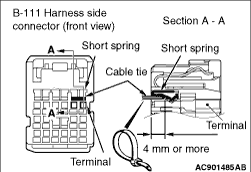
(4)
| caution |
The short spring may not be released due to the insufficient insertion. Therefore, insert
the insulator for 4 mm or more.
|
Insert an insulator (width: 3 mm, thickness: 0.5 mm) such as cable tie between the terminal
51/52 the short spring, and release the short spring.
(5)Connect the negative auxiliary battery terminal.
(6)Electric motor switch to the "ON" position.
(7)
| caution |
Do not insert a test probe into the terminal from its front side directly
as the connector contact pressure may be weakened.
|
Take the measurements below at the B-111 harness side connector.
- Voltage between terminal No.51/52 and body earth
OK: 1 V or less
(8)Disconnect the negative auxiliary battery terminal.
Q.
Is the check result normal?
Go to Step 3
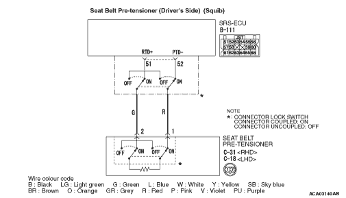
Repair the harness wire between SRS-ECU connector B-111 (terminal No.51 and 52)
and the seat belt pre-tensioner (driver’s side) connector C-18 <LHD> or
C-31 <RHD> (terminal No.2 and 1).
|
|
|
Q.
Is diagnosis code B1443 set?
|
|
|
Replace the SRS-ECU (Refer to ).
|
|
|
|
|
|
An intermittent malfunction is suspected (Refer to GROUP 00, How to Cope with
Intermittent Malfunction ).
|
|
|
|