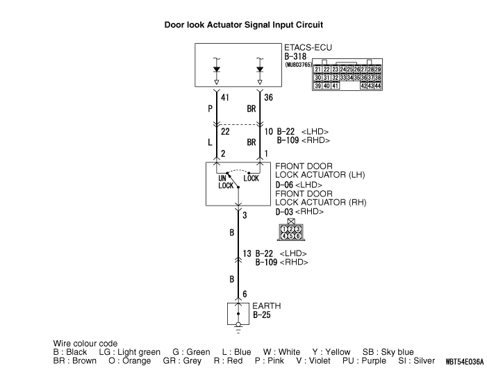
Inspection Procedure 4: The front door lock actuator (driver’s side) signal is not received.
| caution | Before replacing the ECU, ensure
that the power supply circuit, the earth circuit and the communication circuit are normal. |
COMMENTS ON TROUBLE SYMPTOM
- Central door locking
- Keyless entry system
- Room lamp
PROBABLE CAUSES
- Malfunction of the front door lock actuator (driver’s
side)
- Malfunction of the ETACS-ECU
- Damaged harness wires and connectors
DIAGNOSIS PROCEDURE
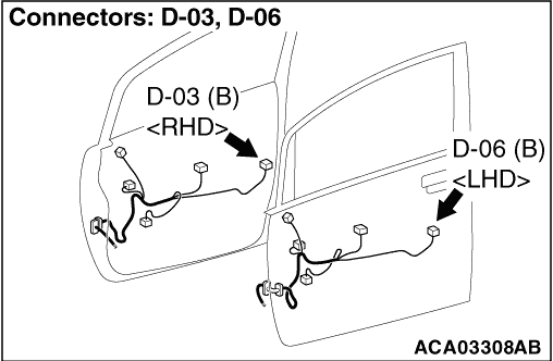
STEP 1. Connector check: D-06 front door lock actuator (LH) <LHD> or D-03 front door lock actuator (RH) <RHD> connector
Q.
Is the check result normal?


STEP 2. Front door lock actuator (driver’s side) check

Q.
Is the check result normal?
STEP 3. Resistance measurement at the D-06 front door lock actuator (LH) <LHD> or D-03 front door lock actuator (RH) <RHD> connector
| (1)Disconnect the connector, and measure at the wiring harness side. |
| (2)Measure the resistance between the D-06 front door lock actuator (RH) connector
terminal No. 3 and the body earth. <LHD> OK: Continuity exists (2 Ω or less) |
| (3)Measure the resistance between the D-03 front door lock actuator (RH) connector
terminal No. 3 and the body earth. <RHD> OK: Continuity exists (2 Ω or less) |
Q.
Is the check result normal?
STEP 4. Wiring harness check between the D-06 front door lock actuator (LH) connector (terminal 3) <LHD> or D-03 front door lock actuator (RH) connector (terminal 3) <RHD> and the body earth
| note | Prior to the wiring harness inspection, check intermediate connector B-22 <LHD>, B-109 <RHD> and
earth connector B-25, and repair if necessary. |
Q.
Is the check result normal?
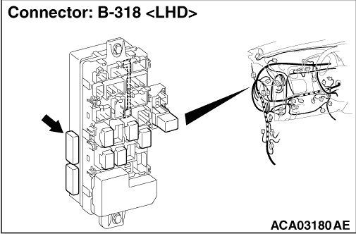
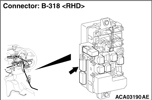
STEP 5. Connector check B-318 ETACS-ECU connector
Q.
Is the check result normal?
STEP 6. Wiring harness check between the D-06 front door lock actuator (LH) connector (terminals 1 or 2) <LHD> or D-03 front door lock actuator (RH) connector (terminals 1 or 2) <RHD> and the B-318 ETACS-ECU connector (terminals 36 or 41).
| note | Prior to the wiring harness inspection, check intermediate connector B-22 <LHD>, B-109 <RHD>, and
repair if necessary. |
Q.
Is the check result normal?
STEP 7. M.U.T.-III data list
|
Q.
Is the check result normal?