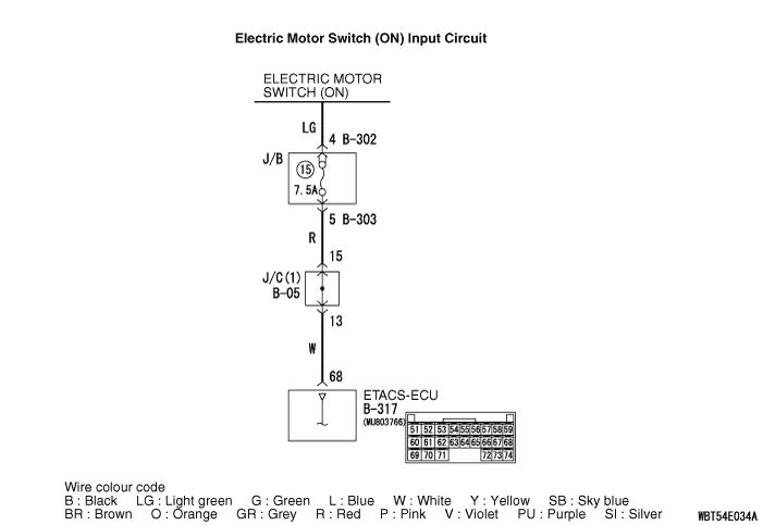
Inspection Procedure 2: The electric motor switch (ON) signal is not received.
| caution | Whenever the ECU
is replaced, ensure that the input signal circuit is normal. |
COMMENTS ON TROUBLE SYMPTOM
PROBABLE CAUSES
- Malfunction of the ETACS-ECU
- Damaged harness wires and connectors
DIAGNOSIS PROCEDURE
STEP 1. Connector check: B-317 ETACS-ECU connector
Q.
Is the check result normal?


STEP 2. Voltage measurement at the B-317 ETACS-ECU connector.
| (1)Disconnect the connector, and measure at the wiring harness side. |
| (2)Turn the electric motor switch to the "ON" position. |
| (3)Voltage between B-317 ETACS-ECU connector terminal No.68 and body earth OK: System voltage |
Q.
Is the check result normal?
STEP 3. Check the wiring harness between B-317 ETACS-ECU connector (terminal 68) and the electric motor switch (IG1).
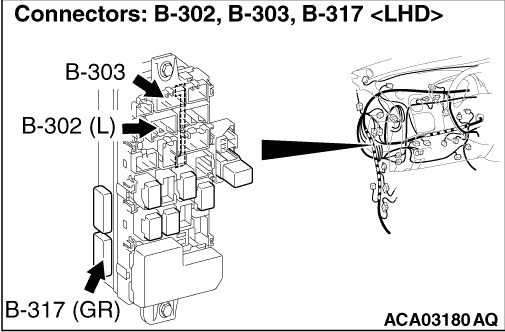
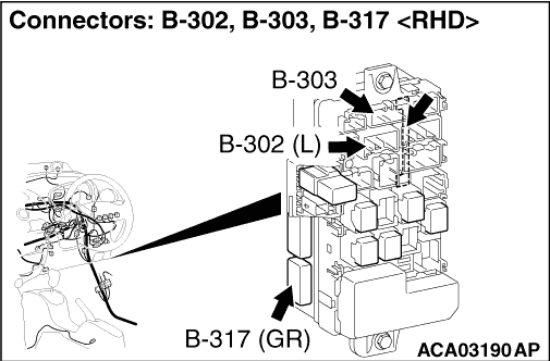
| note | Prior to the wiring harness inspection, check joint connector B-05, junction block connectors
B-302 and B-303, and repair if necessary. |
- Check the power supply line for open circuit.
Q.
Is the check result normal?

STEP 4. M.U.T.-III data list
- Turn the electric motor switch to the "ON" position.
|
Q.
Is the check result normal?