Code No. P0A09: DCDC converter (1)
AUXILIARY BATTERY CHARGING CONTROL CIRCUIT


OPERATION
DIAGNOSIS CODE SET CONDITIONS
- When the DC-DC converter drive stop state continues for
4 seconds or longer while the DC-DC converter driving approval is underway, the diagnosis code No.
P0A09 will be set.
COMMENT ON PAST TROUBLE
- Conduct the actuator test (item 03: Water pump drive,
item 04: Radiator fan 1 drive, item 05: Radiator fan 2 drive) to check the cooling system.
- Visually check the radiator core.
- Check the MCU diagnosis code.
PROBABLE CAUSES
- Damaged wiring harness or connector(s)
- Malfunction of system cooling
- Malfunction of the DC-DC converter
- Malfunction of the EV-ECU
DIAGNOSIS PROCEDURE |
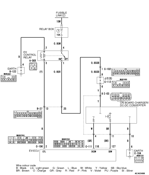
STEP 1. Measure the voltage at E-03 on board charger/DC-DC converter connector. |
| (1)Disconnect the E-03 on board charger/DC-DC converter connector, and measure
the voltage at the wiring harness side. |
| (2)Turn the electric motor switch to the "ON" position. |
| (3)Measure the voltage between the E-03 on board charger/DC-DC converter
connector terminal No. 8 and the body earth. OK: Battery voltage |
Q.
Is the check result normal?
|
 Go to Step 4. Go to Step 4. |
|
 Go to Step 2. Go to Step 2. |
|
STEP 2. Connector check: A-08X EV control relay (relay box) connecter, B-27 intermediate connector, E-03 on board charger/DC-DC converter connector |
Q.
Is the check result normal?
|
| Go to Step 3. |
|
| Repair the damaged connector. Or, correct or replace the relay box. |
|
STEP 3. Check the wiring harness between A-08X EV control relay (relay box) connector terminal No. 1 and E-03 on board charger/DC-DC converter connector terminal No. 8. |
| Check the power supply line for open circuit. |
Q.
Is the check result normal?
|
| Go to Step 4. |
|
| Repair the wiring harness. |
|
STEP 4. Connector check: E-03 on board charger/DC-DC converter connecter, C-111 EV-ECU connector |
Q.
Is the check result normal?
|
| Go to Step 5. |
|
| Repair the damaged connector. |
|
STEP 5. Check the wiring harness between E-03 on board charger/DC-DC converter connector terminal No. 4, 11 and C-111 EV-ECU connector terminal No. 116, 127. |
| Check the signal lines for open circuit. |
Q.
Is the check result normal?
|
| Go to Step 6. |
|
| Repair the wiring harness. |
|
STEP 6. Check the wiring harness between E-03 on board charger/DC-DC converter connector terminal No. 10 and the earth. |
| Check the earth line for open circuit. |
Q.
Is the check result normal?
|
| Go to Step 7. |
|
| Repair the wiring harness. |
|
STEP 7. Check of auxiliary battery charging warning lamp |
| With the connector connected, apply 12 V to the C-111 EV-ECU connector
terminal No. 116. |
|
| OK: The auxiliary battery charging warning lamp goes out. |
Q.
Is the check result normal?
|
Replace the on board charger/DC-DC converter. (Refer to  .)
Then go to Step 9. .)
Then go to Step 9. |
|
| Go to Step 8. |
|
STEP 8. Diagnosis code recheck |
| Check again if the diagnosis code is set to the EV-ECU. |
| (1)Erase the stored diagnosis code. |
| (2)Set the electric motor switch from the "LOCK" (OFF) position to the "ON" position. |
| (3)Check if the diagnosis code is set. |
Q.
Is the diagnosis code set?
|
| Replace the EV-ECU. (Refer to .) Then go
to Step 9. |
|
| Intermittent malfunction (Refer to GROUP 00 - How to Use Troubleshooting/Inspection
Service Points - How to Cope with Intermittent Malfunction .) |
|
STEP 9. Diagnosis code recheck |
| Check again if the diagnosis code is set to the EV-ECU. |
| (1)Erase the stored diagnosis code. |
| (2)Set the electric motor switch from the "LOCK" (OFF) position to the "ON" position. |
| (3)Check if the diagnosis code is set. |
Q.
Is the diagnosis code set?
|
| Return to Step 1. |
|
| The diagnosis is complete. |
|