Code No. P2122:
Accelerator pedal position sensor (main) low input
Code No. P2123: Accelerator pedal
position sensor (main) high input
ACCELERATOR PEDAL POSITION SENSOR CIRCUIT



OPERATION
- The accelerator pedal position sensor (main) is supplied
with the 5-V power from the EV-ECU, converts the accelerator pedal position sensor opening into
the voltage, and outputs it to the EV-ECU.
DIAGNOSIS CODE SET CONDITIONS
- If the accelerator pedal position sensor (main) output
voltage of 0.2 V or less continues, the diagnosis code No. P2122 will be set.
- If the accelerator pedal position sensor (main) output voltage of 4.8 V or more continues,
the diagnosis code No. P2123 will be set.
PROBABLE CAUSES
- Damaged wiring harness or connector(s)
- Malfunction of the accelerator pedal position sensor (main)
- Malfunction of the EV-ECU
DIAGNOSIS PROCEDURE |
STEP 1. M.U.T.-III data list |
Check the service data for the accelerator pedal position sensor (main). (Refer to  .) .) |
Data list
|
Q.
Is the check result normal?
|
 Intermittent malfunction (Refer to GROUP 00 - How to Use Troubleshooting/Inspection
Service Points - How to Cope with Intermittent Malfunction .) Intermittent malfunction (Refer to GROUP 00 - How to Use Troubleshooting/Inspection
Service Points - How to Cope with Intermittent Malfunction .) |
|
 Go to Step 2. Go to Step 2. |
|
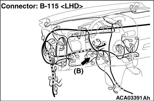
STEP 2. Measure the voltage at B-115 accelerator pedal position sensor (main) connector. |
| (1)Disconnect the B-115 accelerator pedal position sensor (main) connector, and measure
the voltage at the wiring harness side. |
| (2)Turn the electric motor switch to the "ON" position. |
| (3)Measure the voltage between the B-115 accelerator pedal position sensor (main)
connector terminal No. 1 and the body earth. OK: 4.9 to 5.1 V |
Q.
Is the check result normal?
|
| Go to Step 5. |
|
| Go to Step 3. |
|
STEP 3. Connector check: B-115 accelerator pedal position sensor (main) connector, C-108 EV-ECU connector |
Q.
Is the check result normal?
|
| Go to Step 4. |
|
| Repair the damaged connector. |
|
STEP 4. Check the wiring harness between C-108 EV-ECU connector terminal No. 42 and B-115 accelerator pedal position sensor (main) connector terminal No. 1. |
| Check the power supply line for open circuit. |
Q.
Is the check result normal?
|
| Go to Step 5. |
|
| Repair the wiring harness. |
|
STEP 5. Check the wiring harness between C-108 EV-ECU connector terminal No. 48, 59 and B-115 accelerator pedal position sensor (main) connector terminal No. 2, 3. |
| Check the signal lines for open circuit and short circuit. |
Q.
Is the check result normal?
|
| Replace the accelerator pedal. (Refer to GROUP 17 - Accelerator Pedal
Removal and Installation .) Then go to Step 6. |
|
| Repair the wiring harness. |
|
STEP 6. Diagnosis code recheck |
| Check again if the diagnosis code is set to the EV-ECU. |
| (1)Erase the stored diagnosis code. |
| (2)Set the electric motor switch from the "LOCK" (OFF) position to the "ON" position. |
| (3)Check if the diagnosis code is set. |
Q.
Is the diagnosis code set?
|
| Replace the EV-ECU. (Refer to .) Then go
to Step 7. |
|
| The diagnosis is complete. |
|
STEP 7. Diagnosis code recheck |
| Check again if the diagnosis code is set to the EV-ECU. |
| (1)Erase the stored diagnosis code. |
| (2)Set the electric motor switch from the "LOCK" (OFF) position to the "ON" position. |
| (3)Check if the diagnosis code is set. |
Q.
Is the diagnosis code set?
|
| Return to Step 1. |
|
| The diagnosis is complete. |
|