REMOVAL AND INSTALLATION


danger When servicing the high-voltage system parts, be sure to wear the specified protection equipment and disconnect the service plug to interrupt the high-voltage supply (Refer to ).
caution When the inverter is replaced, register the ID code.(Refer to GROUP 54A, On-vehicle Service - How to register key ID .)
Pre-removal operation
  • Coolant draining (Refer to GROUP 14 - On-vehicle Service, Coolant Replacement .)

Post-installation operation
  • Coolant refilling (Refer to GROUP 14 - On-vehicle Service, Coolant Replacement .)


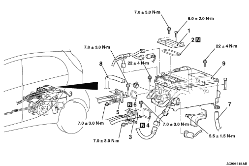
Removal steps


1.
Service lid


2.
O-ring
<<A>>
>>C<<
3.
Motor (electric motor unit) cable connection


4.
O-ring
<<A>>
>>C<<
5.
Main battery cable connection


6.
O-ring
<<B>>
>>B<<
7.
Radiator piping hose L connection
<<B>>
>>B<<
8.
Radiator piping hose M connection

>>A<<
9.
Inverter

REMOVAL SERVICE POINTS


<<A>> CABLE DISCONNECTION


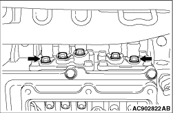
1.Remove the inner cable mounting bolts (5 locations).


2.
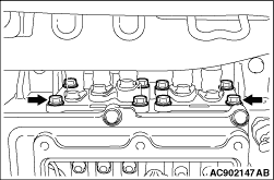
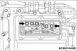
caution Do not remove the mounting bolts (5 locations) shown in the figure.
Remove the outer cable mounting bolts (8 locations).
3.Pull out the cable from the inverter.

<<B>> RADIATOR PIPING HOSE DISCONNECTION


Put a mating mark before removal as shown in the figure in order to assemble the hose and hose clips to the original positions.

INSTALLATION SERVICE POINTS


>>A<< INVERTER INSTALLATION


Securely install the breather hose of the motor (electric motor unit) onto the hose clamp of the inverter.

>>B<< RADIATOR PIPING HOSE CONNECTION


1.Insert the hose to each pipe up to the convex portion.
2.Align the mating marks on the hose and hose clips and install the hose without twisting the hose.

>>C<< CABLE CONNECTION


1.Install the cable onto the inverter.
2.Install the outer cable mounting bolts and inner cable mounting bolts in this order and tighten them to the specified torque.
Tightening torque: 7.0 ± 3.0 N·m