|
|
Check Conditions
- The main battery cooling fan relay is turned ON.
- The following diagnosis codes are not set.
- P1A47: Power supply of main battery cooling fan relay abnormal
(short circuits to power supply system, open circuits)
- P1A4E: Power supply of main battery cooling fan relay abnormal (short circuits to
earth system)
|
|
|
Judgement Criterion
- For more than 5 seconds, the PWM output signal of the main battery cooling fan is
10 % (while the fan is being driven). The output of the rotational speed is less than
2.0 V (less than 1,645 r/min or equivalent).
|
|
|
- The main battery cooling fan relay is failed.
- The main battery cooling fan is failed.
- Open circuits of main battery cooling fan relay circuit, short circuits to earth
or damage; poor contact of connector.
- Open circuits of main battery cooling fan circuit, short circuits to earth or damage;
poor contact of connector.
- The BMU is failed.
|
|
|
Q.
Is the check result normal?
|
|
|
- Check main battery cooling fan relay itself (Refer to
 ). ).
|
|
|
Q.
Is the check result normal?
|
|
|
 Replace the main battery cooling fan relay. Replace the main battery cooling fan relay.
|
|
|
|
|
|
- Remove the relay, and measure at relay box side.
- Voltage between terminal No. 4 and earth.
|
|
|
Q.
Is the check result normal?
|
|
|
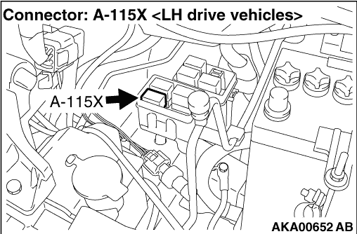
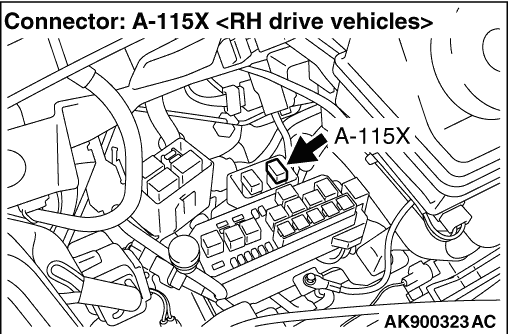
Check and repair harness between auxiliary
battery and A-115X (terminal No. 4) main battery cooling fan relay connector.
- Check power supply line for open circuit, short circuit to earth
|
|
|
|
|
|
Q.
Is the check result normal?
|
|
|
- Disconnect connector, and measure at harness side.
- Remove the A-115X main battery cooling fan relay, and short-circuit the terminal
4 - 3 at the relay box side.
- Voltage between terminal No. 1 and earth.
|
|
|
Q.
Is the check result normal?
|
|
|
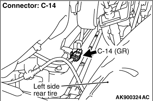
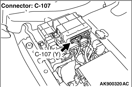
Check intermediate connector A-107, and repair
if necessary. If intermediate connector is normal, check and repair harness between A-115X (terminal
No. 3) main battery cooling fan relay connector and C-14 (terminal No. 1) main battery cooling
fan connector.
- Check output line for open circuit, short circuit to earth.
|
|
|
|
|
|
- Disconnect connector, and measure at harness side.
- Resistance between terminal No. 4 and earth.
|
|
|
OK: Continuity (2 Ω less)
|
|
|
Q.
Is the check result normal?
|
|
|
Check intermediate connector C-104, and repair
if necessary. If intermediate connector is normal, check and repair harness between C-14 (terminal No.
4) main battery cooling fan connector and body earth.
- Check earthing line for open circuit and damage.
|
|
|
|
|
|
- Check power supply line for damage.
|
|
|
Q.
Is the check result normal?
|
|
|
- Check output line for damage.
|
|
|
Q.
Is the check result normal?
|
|
|
- Use special tool test harness (MB991658) to connect C-14 main battery cooling
fan connector, and measure at pick-up harness.
- For several seconds right after starting the regular charge.
- Voltage between terminal No. 2 and earth.
|
|
|
OK: The wave pattern must be the same as that described in Inspection Procedure
Using an Oscilloscope ().
|
|
|
Q.
Is the check result normal?
|
|
|
Q.
Is the check result normal?
|
|
|
- Check signal line for open circuit, short circuit to earth and damage.
|
|
|
Q.
Is the check result normal?
|
|
|
Q.
Is the diagnosis code set?
|
|
|
Intermittent malfunction (Refer to GROUP 00 - How to Use Troubleshooting/Inspection
Service Points - How to Cope with Intermittent Malfunctions ).
|
|
|
|
|
|
- After replacing the BMU, reconfirm whether the diagnosis codes are set.
|
|
|
Q.
Is the diagnosis code set?
|
|
|
 Replace the main battery. Replace the main battery.
|
|
|
|
|
|
- Measure BMU terminal voltage.
- Right after starting the regular charge.
- Voltage between terminal No. 21 and earth.
|
|
|
OK: 2 V or more → 1 V or less (After several seconds elapse)
|
|
|
Q.
Is the check result normal?
|
|
|
- Refer to Data List Reference Table .
- Item 32: Main battery cooling fan rotational speeds
|
|
|
Q.
Is the check result normal?
|
|
|
Intermittent malfunction (Refer to GROUP 00 - How to Use Troubleshooting/Inspection
Service Points - How to Cope with Intermittent Malfunctions ).
|
|
|
|
|
|
Q.
Is the check result normal?
|
|
|
- Check output line for open circuit, short circuit to earth and damage.
|
|
|
Q.
Is the check result normal?
|
|
|
Q.
Is the diagnosis code set?
|
|
|
Replace the main battery.
|
|
|
|
|
|
Intermittent malfunction (Refer to GROUP 00 - How to Use Troubleshooting/Inspection
Service Points - How to Cope with Intermittent Malfunctions ).
|
|
|
|