|
|
1.Remove the engine air intake pipe.
|
|
|
2.Remove the inlet manifold.
|
|
|
3.Remove the injection pipe.
|
|
|
4.Remove the timing belt cover.
|
|
|
5.Remove the rocker cover.
|
|
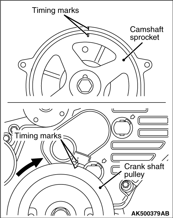
6.Align the camshaft sprocket timing marks and set the No. 1 cylinder at top dead centre.
| caution |
The crankshaft should always be turned in a clockwise direction.
|
|
|
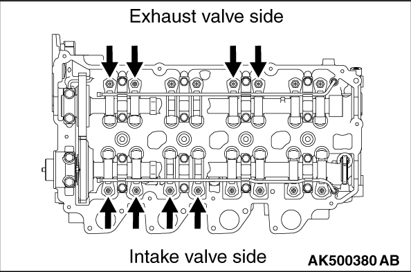
7.Measure the valve clearance.
If the valve clearance is not as specified, loosen the rocker arm lock nut and adjust
the clearance using a thickness gauge between the cam shaft and the roller while turning the adjusting
screw.
Standard value (cold engine):
Intake valve: 0.09 mm
Exhaust valve: 0.14 mm
|
|
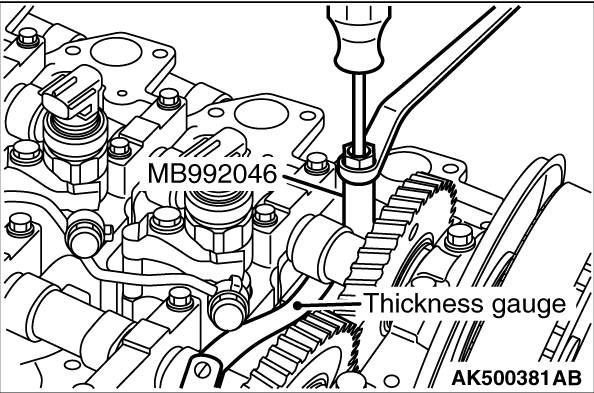
8.While holding the adjusting screw with a screwdriver to prevent it from turning, tighten
the lock nut to the specified torque using a valve adjusting socket. (MB992046)
Tightening torque: 15 ± 3 N·m
| caution |
Pay special attention that the tightening torque is not beyond
this valve. If the tightening torque is beyond the valve, the valve stem would possibly bend.
|
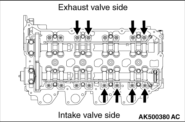
9.Turn the crankshaft 360° clockwise to bring No. 4 cylinder to the top dead
centre position.
|
|
10.Measure the valve clearances at the places indicated by arrows in the illustration. If
the clearance is not within the standard value, repeat steps 7 and 8 above.
|
|
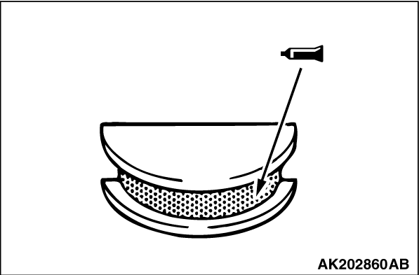
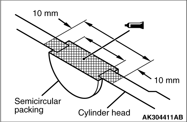
11.Apply specified sealant to the section of the semi-circular packing shown in the illustration.
Specified sealant: 3M ATD Part No. 8660 or equivalent
12.Install the rocker cover.
13.Install the timing belt cover.
14.Install the injection pipe, the injection pipe to the specified torque.
Tightening torque: 35 ± 5 N·m
| caution |
- The reinstallation histories
of the removed injection pipe are up to five times. To count how many times the injection pipe
is reinstalled, record the number of the reinstallation histories on the service booklet by
adding this latest number of the histories, which is usually "1", to the previous one. Use a
new injection pipe when the total reinstallation history numbers reach five times, or when the
injector or common rail is replaced. In this case, record " a new injector pipe, the number
of the reinstallation histories is zero" on the service booklet.
- When the injection pipe is reinstalled, confirm there is no foreign material on
the seal surface or in the pipe and then install it not to deviate from the axis, fitting the seal
surface.
|
15.Install the inlet manifold.
| note |
Install a new gasket
|
16.Install the engine air intake pipe.
17.After the ignition switch is in "LOCK" (OFF) position, connect the M.U.T.-III to the
diagnosis connector.
18.Start the engine, and let it run at idle.
19.Select SPECIAL FUNCTION from the function menu.
20.Select FUEL LEAKAGE CHECK from SPECIAL FUNCTION menu to execute the test.
| note |
During the test, the engine speed and the fuel pressure is 2, 000 r/min and 180Mpa for
20 seconds respectively.
|
21.Confirm there is no fuel leak from the joint for the injection pipe.
|