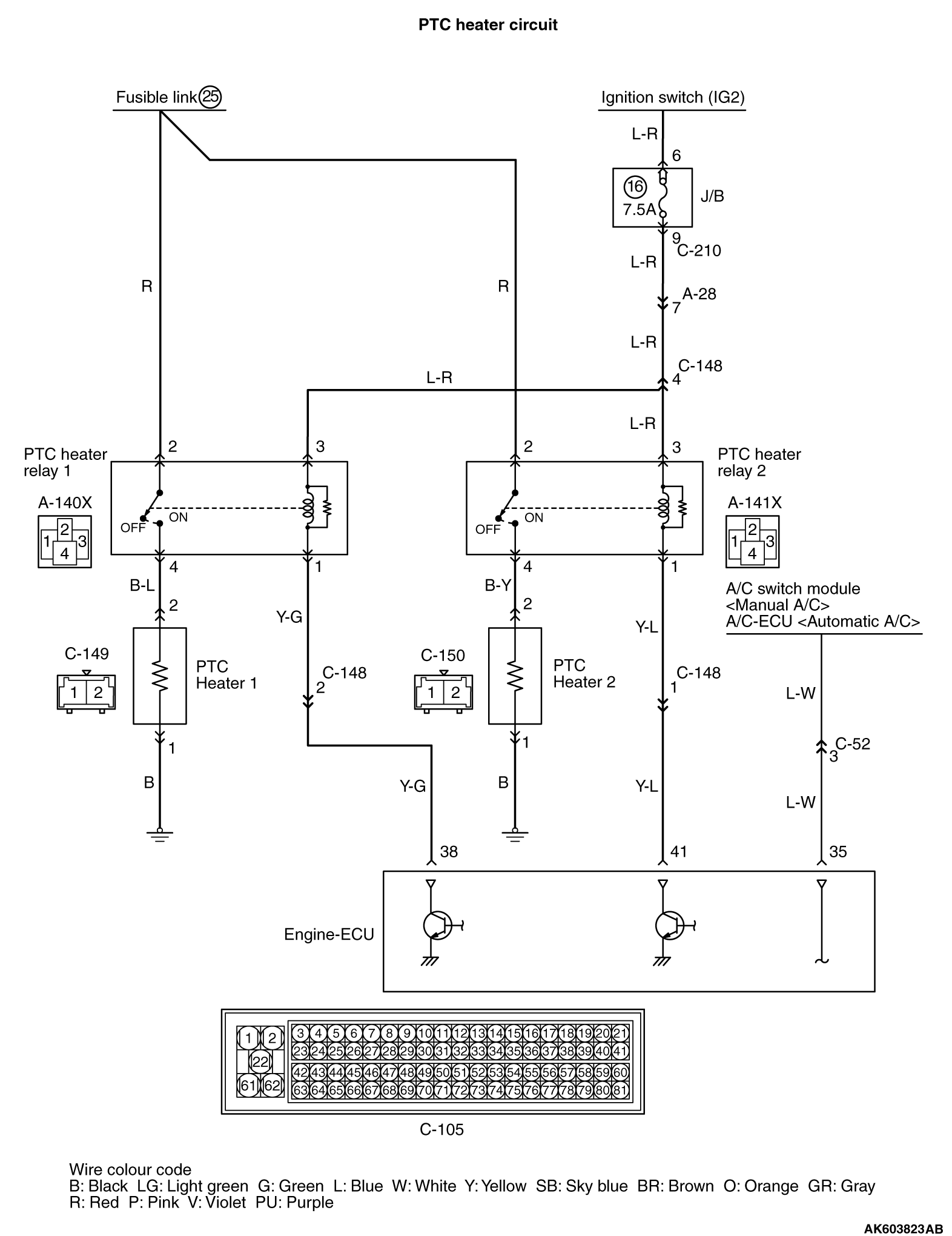
Inspection Procedure 24: PTC Heater Relay System <Vehicle with PTC Heater>


OPERATION


  • When the PTC heater operation request signal (battery voltage) is input into the engine-ECU (terminal No. 35) from the A/C switch module<manual A/C> or A/C-ECU<automatic A/C>, the engine-ECU turns ON the PTC heater relay 1 and 2 after satisfying all the operation conditions.
  • Operation conditions of PTC heater relay 1
  1. Engine coolant temperature is under 80°C
  2. 2 seconds later after the engine has start up.
  3. The PTC heater request signal has been input continuously 2 seconds or more
  4. The battery voltage continues to be 12.3 V or more for 12 seconds or more.
Operation conditions of PTC heater relay 2
  1. Engine coolant temperature is under 75°C.
  2. The PTC heater 1 has been ON continuously 45 seconds or more.
  3. Heater switch (warm up switch) is ON or vehicle speed is 20km/h or more.
  4. The battery voltage continues to be 12.9 V or more for 12 seconds or more.

PROBABLE CAUSES


  • Failed PTC heater relay
  • Failed PTC heater
  • Damaged harness (Open circuit between PTC heater relay and engine-ECU, PTC heater relay and J/B, PTC heater relay and PTC heater, PTC heater and body earth, and open circuit between PTC heater relay and fusible link 25.
  • Damaged connector (PTC heater relay connector, PTC heater connector, engine-ECU connector).
  • Failed engine-ECU

DIAGNOSIS PROCEDURE


STEP 1. M.U.T.-III data list


  • Refer to Data List Reference Table .

  1. Item 76 PTC heater 1 relay
  2. Item 77 PTC heater 2 relay

Q. Is the check result normal?

Go to Step 2 .
Check PTC heater system (Refer to GROUP 55A - Troubleshooting - Trouble Symptom Chart ).

STEP 2. PTC heater 1 operation check


  • Disconnect the C-105 connector.
  • Using the jumper wire, connect terminal No. 38 to earth.
OK: The PTC heater 1 operates.

Q. Is the check result normal?

Go to Step 3 .

Check PTC heater system (Refer to GROUP 55A - Troubleshooting - Trouble Symptom Chart ).

STEP 3. PTC heater 2 operation check.


  • Disconnect the C-105 connector.
  • Using the jumper wire, connect terminal No.41 to earth.
OK: The PTC heater 2 operates.

Q. Is the check result normal?

Go to Step 4 .

Check PTC heater system (Refer to GROUP 55A - Troubleshooting - Trouble Symptom Chart ).

STEP 4. Connector check: C-105 engine-ECU connector.


Q. Is the check result normal?

Go to Step 5 .

Repair or replace.

STEP 5. Check the trouble symptoms.


Q. Does trouble symptom persist?

Replace the engine-ECU. When the engine-ECU is replaced, write the chassis number (Refer to GROUP 00 - How to Perform Chassis Number Writing ). After replacing the engine-ECU, register the injector identification code and learn fuel injection (Refer to GROUP 00 - Precautions Before Service - What The Common Rail Engine Learns ).
Intermittent malfunction (Refer to GROUP 00 - How to Use Troubleshooting/Inspection Service Points - How to Cope with Intermittent Malfunction ).