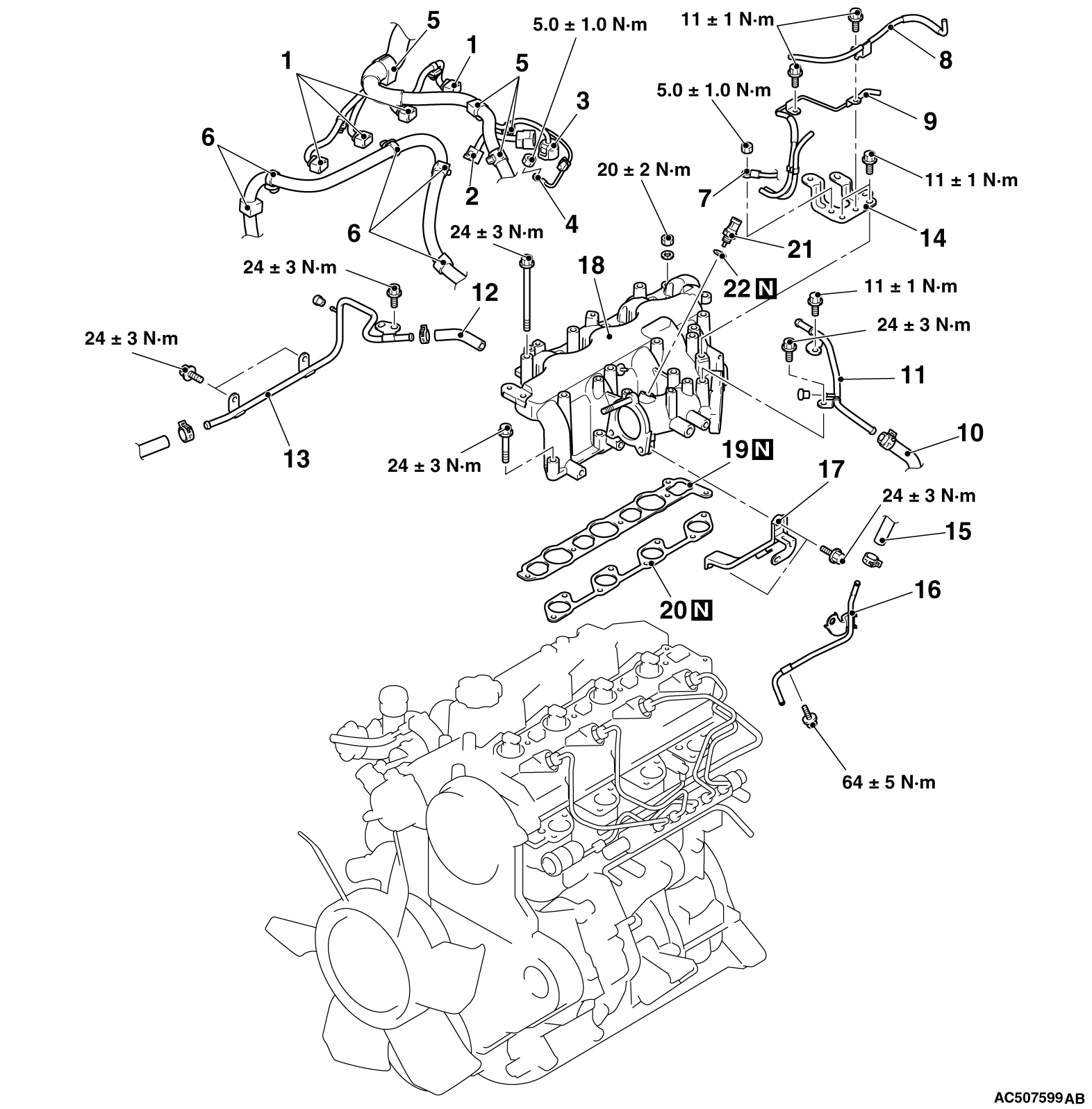
REMOVAL AND INSTALLATION


Pre-removal Operation
  • Engine Coolant Draining (Refer to GROUP 14 - On-vehicle Service, Engine Coolant Replacement ).
  • Throttle Body Removal (Refer to GROUP 13A - Throttle Body ).
  • EGR Valve and EGR Pipe Removal (Refer to GROUP 17 - EGR Valve and EGR Cooler ).
  • Windshield Wiper Removal (Refer to GROUP 51 - Windshield Wiper ).
  • Cowl Top Panel Front Removal

Post-installation Operation
  • Cowl Top Panel Front Installation
  • Windshield Wiper Installation (Refer to GROUP 51 - Windshield Wiper ).
  • EGR Valve and EGR Pipe Installation (Refer to GROUP 17 - EGR Valve and EGR Cooler ).
  • Throttle Body Installation (Refer to GROUP 13A - Throttle Body ).
  • Engine Coolant Refilling (Refer to GROUP 14 - On-vehicle Service, Engine Coolant Replacement ).
  • Air Bleeding from Fuel Line (Refer to GROUP 13A - On-vehicle Service, Evacuation of Air from Fuel Line ).


Removal steps


1.
Fuel injector connector


2.
Air temperature sensor connector


3.
Fuel pressure sensor harness connector


4.
Glow plug terminal


5.
Control wiring harness clamp


6.
Battery cable clamp


7.
Earth cable connection


8.
Vacuum hose and pipe assembly


9.
Vacuum hose and pipe assembly


10.
Brake booster vacuum hose connection


11.
Vacuum pipe B


12.
Vacuum hose


13.
Vacuum pipe A


14.
Engine cover stay A
<<A>>

15.
Fuel hose D connection


16.
Fuel inlet pipe


17.
Inlet manifold stay

>>A<<
18.
Inlet manifold assembly


19.
Inlet manifold helical gasket


20.
Inlet manifold tangential gasket


21.
Air temperature sensor


22.
Gasket

REMOVAL SERVICE POINT


<<A>> FUEL HOSE D DISCONNECTION


caution When disconnecting the fuel hose D, the fuel pressure in the fuel line is high. Thus, wait for 3 minutes or longer after the engine is stopped, and cover the fuel hose D with a rag or similar materials to prevent the fuel splash, and then disconnect the fuel hose D.

INSTALLATION SERVICE POINT


>>A<< INLET MANIFOLD ASSEMBLY INSTALLATION


1.As shown in the illustration, temporarily tighten to 6.0 ± 1.0 N·m the bolts located at side A.
2.As shown in the illustration, tighten the bolts and nuts located at side B to the specified torque.
Tightening torque:
    24 ± 3 N·m <Bolts>
    20 ± 2 N·m <Nuts>
3.As shown in the illustration, tighten the bolts located at side A to the specified torque.
Tightening torque: 24 ± 3 N·m