|
|
Item 26: Overdrive switch (Refer to data list reference table  ). ).
|
|
|
Q.
Is the check result normal?
|
|
|
 Intermittent malfunction (Refer to GROUP 00 -
How to Cope with Intermittent
Malfunction ). Intermittent malfunction (Refer to GROUP 00 -
How to Cope with Intermittent
Malfunction ).
|
|
|
|
|
|
Q.
Is the check result normal?
|
|
|
 Replace the high/low detection switch. Replace the high/low detection switch.
|
|
|
|
|
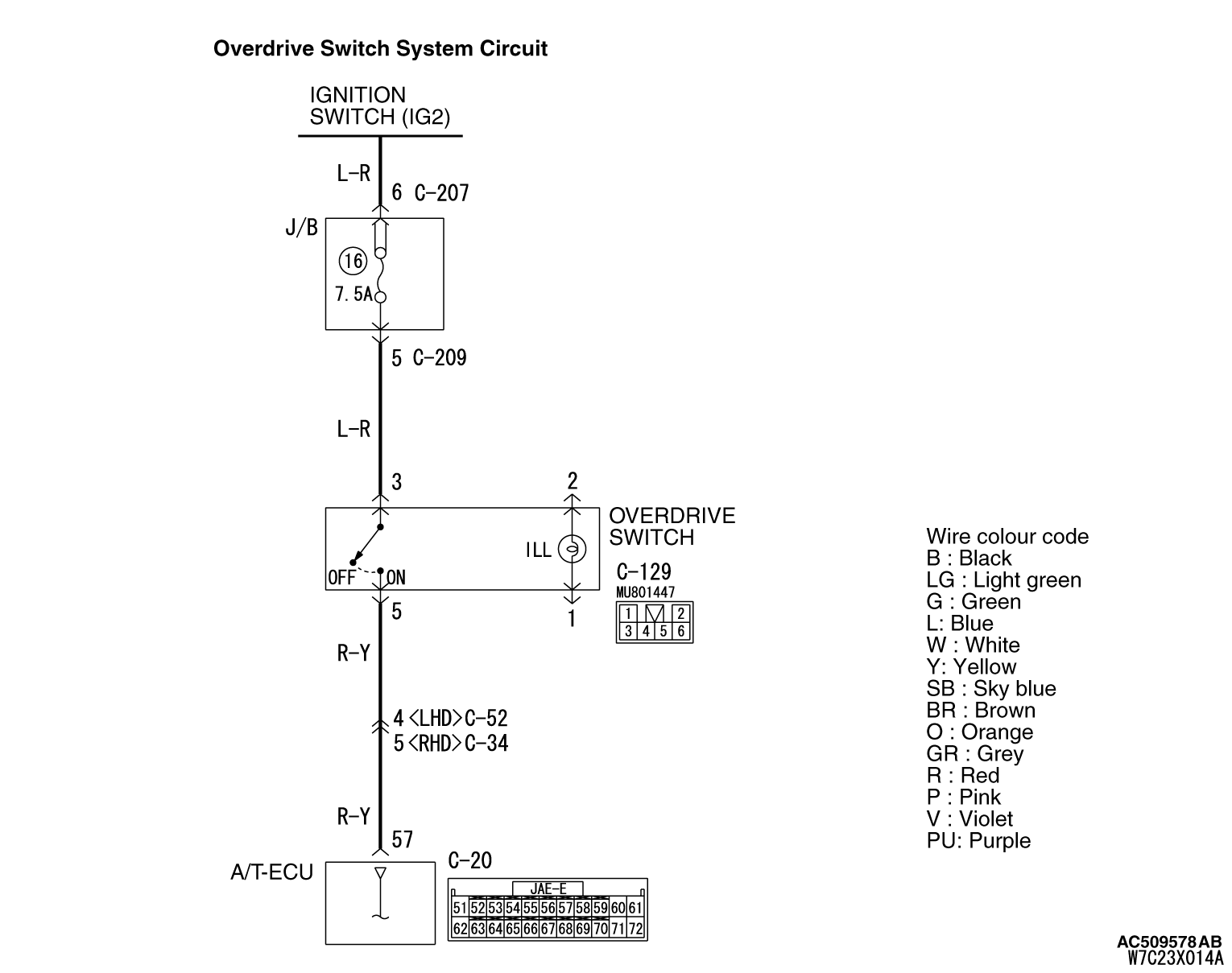
(1)Disconnect the connector, and measure the voltage between terminal 3 and earth at the
wiring harness side.
(2)Turn the ignition switch to the ON position.
OK: System voltage
Q.
Is the check result normal?
Go to Step 6.
Go to Step 4.
|
|
Check for the contact with terminals.
Q.
Is the check result normal?
Go to Step 5.
Repair the defective connector.
|
|
Check the power supply line for short or open circuit.
Q.
Is the check result normal?
Go to Step 6.
Repair the wiring harness.
|
|
|
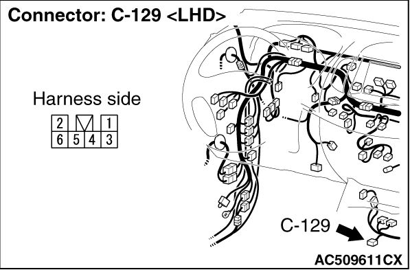
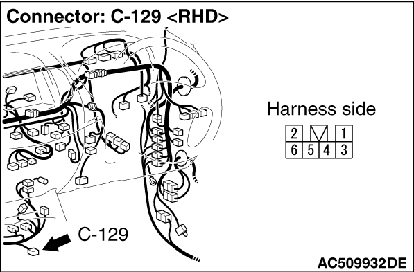
(1)Disconnect high/low detection switch connector C-129.
|
|
|
(2)Turn the ignition switch to the ON position.
|

|
(4)Measure the voltage between A/T-ECU connector C-20 terminal No.57 and earth.
OK: System voltage
Q.
Is the check result normal?
Go to Step 7.
Go to Step 8.
|
|
|
Item 26: Overdrive switch (Refer to data list reference table ).
|
|
|
Q.
Is the check result normal?
|
|
|
Intermittent malfunction (Refer to GROUP 00 -
How to Cope with Intermittent
Malfunction ).
|
|
|
|
|
Check for the contact with terminals.
Q.
Is the check result normal?
Go to Step 9.
Repair the defective connector.
|
|
Check the power supply line for short or open circuit.
Q.
Is the check result normal?
Go to Step 7.
Repair the wiring harness.
|