Code No. C1226: Control Solenoid Valve (FR) Pressure Holding System
Code No.C1231: Control Solenoid Valve (FR) Decompressing System
Code No.C1236: Control Solenoid Valve (FL) Pressure Holding System
Code No.C1241: Control Solenoid Valve (FL) Pressure Reducing System
Code No.C1246: Control Solenoid Valve (RR) Pressure Holding System
Code No.C1251: Control Solenoid Valve (RR) Pressure Reducing System
Code No.C1256: Control Solenoid Valve (RL) Pressure Holding System
Code No.C1261: Control Solenoid Valve (RL) Decompressing System
Code No.C1278: Valve Relay System Stuck Off
Code No.C1279: Valve Relay System Stuck On
| caution | If there is any problem in the CAN bus lines, an incorrect diagnosis code may be set. Diagnose the CAN bus lines before the diagnosis codes (Refer to GROUP 54C, CAN bus-line diagnostic flow  ). ). |
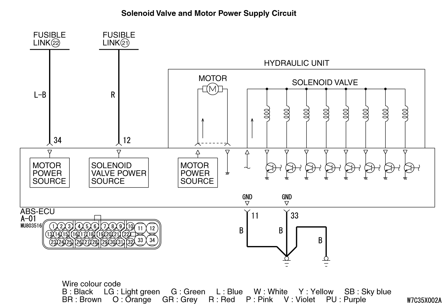
OPERATION
- The ABS-ECU contains the power supply circuit for the solenoid valve. The solenoid valve is energized by the valve relay, which is incorporated in the ABS-ECU.
- The valve relay, which is incorporated in the ABS-ECU, is always energizing the solenoid valve unless the initial check is in progress when the ignition switch is turned on.
- The ABS-ECU activates the solenoid valve by turning on its driving transistor.
DIAGNOSIS CODE SET CONDITIONS
Code No.C1226, C1231, C1236, C1241, C1246, C1251, C1256, C1261
- The output of the each solenoid valve does not change when the solenoid valve is "ON" and the solenoid valve monitor is "ON"
- The solenoid valve relay monitor is "OFF" when the solenoid valve relay is "ON"
- The solenoid valve relay monitor is "ON" when the solenoid valve relay is "OFF"
PROBABLE CAUSES
- Damaged wiring harness or connector
- Malfunction of the hydraulic unit assembly (integrated with ABS-ECU)
DIAGNOSIS |
STEP 1. M.U.T.-III CAN bus diagnostics. |
  |
(2)Turn the ignition switch to the "ON" position. (3)Diagnose the CAN bus line. (4)Turn the ignition switch to the "LOCK" (OFF) position. Q.
Is the check result normal? Go to Step 3. Go to Step 3. Repair the CAN bus line (Refer to GROUP 54C, CAN bus line Diagnostic flow ). Then go to Step 2. Repair the CAN bus line (Refer to GROUP 54C, CAN bus line Diagnostic flow ). Then go to Step 2. |
STEP 2. Check whether the diagnosis code is reset. |
|
(2)Erase the diagnosis code. (3)Turn the ignition switch to the "LOCK" (OFF) position. (4)Turn the ignition switch to the "ON" position. (5)Check if the diagnosis code is set. (6)Turn the ignition switch to the "LOCK" (OFF) position. Q.
Is code No.C1226, C1231, C1236, C1241, C1246, C1251, C1256, C1261, C1278 or C1279 set?Replace the hydraulic unit assembly (integrated with ABS-ECU). Then go to Step 3.The procedure is complete. |
STEP 3. Check whether the diagnosis code is reset. |
|
Check again if the diagnosis code is set. (1)Turn the ignition switch to the "ON" position. (2)Erase the diagnosis code. (3)Turn the ignition switch to the "LOCK" (OFF) position. (4)Turn the ignition switch to the "ON" position. (5)Check if the diagnosis code is set. (6)Turn the ignition switch to the "LOCK" (OFF) position. Q.
Is code No.C1226, C1231, C1236, C1241, C1246, C1251, C1256 or C1261 set?Go to Step 1.The procedure is complete. |