|
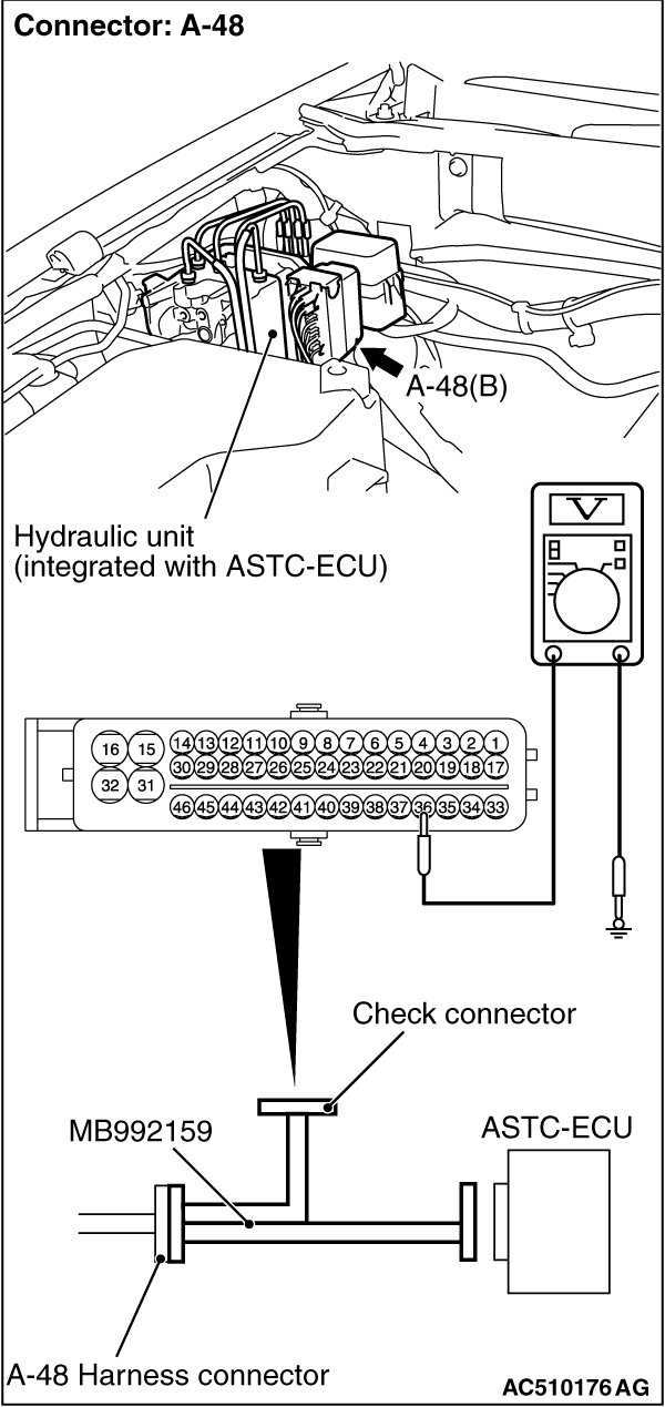
(1)Disconnect the connector A-48, and connect special tool ASC Check Harness (MB992159) to
the wiring harness-side connector.
| note |
Do not connect special tool ASC Check Harness (MB992159) to the ASTC-ECU.
|
(2)Turn the ignition switch to the "ON" position.
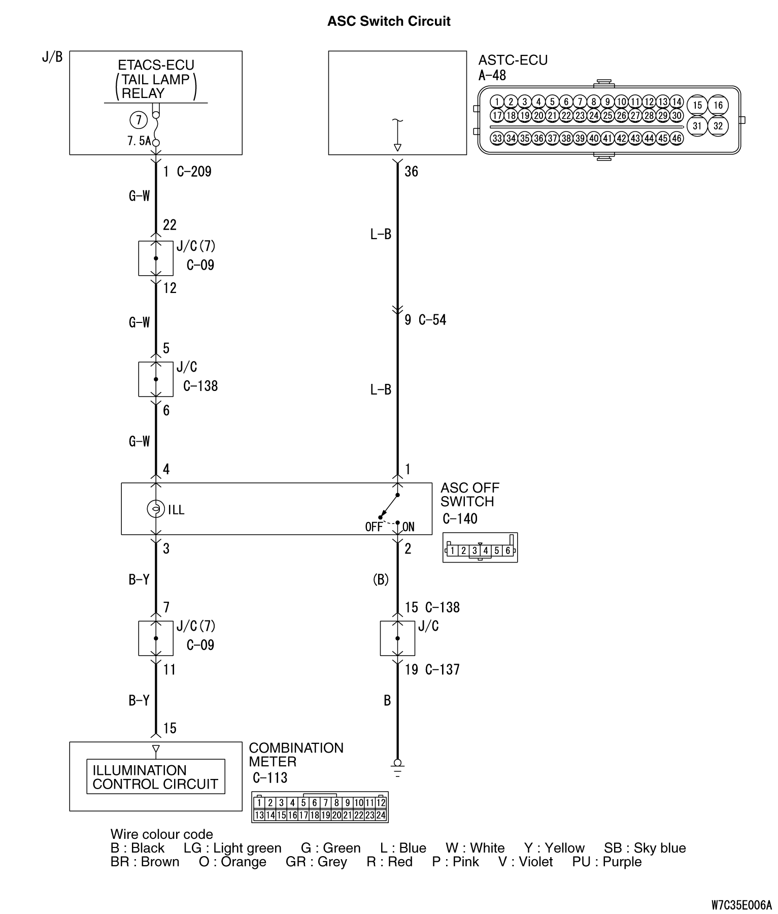
(3)Measure the terminal voltage between special tool MB992159 connector terminal 36
(ASTC-ECU connector A-48 terminal 36) and earth.
OK:
- When the ASC switch is not pressed, the voltage should measure battery positive
voltage (approximately 12 volts.)
- When the ASC switch is pressed, the voltage should measure 1 volt or less.
(4)Turn the ignition switch to the "LOCK" (OFF) position.
(5)Disconnect special tool MB992159 between the ASTC-ECU and the body-side harness
connector.
(6)Connect all the connectors from the ASTC-ECU.
Q.
Is the check result normal?
 Go to Step 6. Go to Step 6.
 Go to Step 2. Go to Step 2.
|
|
|
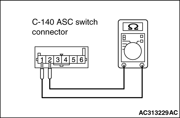
(1)Remove the ASC switch. (Refer to  .) .)
|
|
(2)Connect an ohmmeter to the ASC switch between terminals 1 and 2.
(3)Check for continuity between terminals 1 and 2 when the TCL switch is operated.
OK:
- There is no continuity between terminals 1 and 2 when the ASC switch is not pressed.
- There is continuity between terminals 1 and 2 when the ASC switch is pressed.
Q.
Is the check result normal?
Install the ASC switch (Refer to .) Then go to Step
6.
Replace the ASC switch (Refer to .) Then go to Step
7.
|

|
Q.
Is the check result normal?
Go to Step 4.
Repair or replace the faulty connector. Then go to Step 7.
|
|
Q.
Is the check result normal?
Go to Step 5.
Repair the damaged harness wire. Then go to Step 7.
|
|
Q.
Is the check result normal?
Go to Step 6.
Repair the damaged harness wire. Then go to Step 7.
|
|
|
Q.
Is ASC and ATC system cancelled when the ASC switch is push on?
|
|
|
It can be assumed that this malfunction is intermittent. (Refer to GROUP 00, How
to Use Troubleshooting/Inspection Service Points -
How to Cope with Intermittent
Malfunction ).
|
|
|
|
|
|
Replace the hydraulic unit (integrated with ASTC-ECU). Then go to Step 7.
|
|
|
|
|
|
Q.
Does ASC and ATC system cancelled, when the ASC switch is push on?
|
|
|
The procedure is complete.
|
|
|
|