|
|
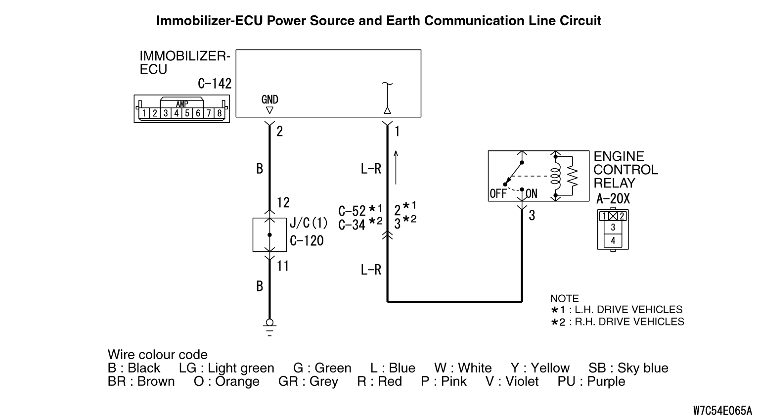
The power supply and earth circuit to the immobilizer ECU may be defective.
|
|
|
Damaged harness wires and connectors
|


|
Q.
Is the check result normal?
 Go to Step 2. Go to Step 2.
 Repair the defective connector. Repair the defective connector.
|
|
(1)Disconnect the immobilizer-ECU connector C-142 and measure the voltage at immobilizer-ECU connector C-142 harness side.
(2)Turn the ignition switch to “ON” position.
|

|
(3)Measure the voltage between terminal 1 and earth.
OK: Battery voltage
Q.
Is the check result normal?
Go to Step 5.
Go to Step 3.
|

|
Q.
Is the check result normal?
Go to Step 4.
Repair the defective connector.
|

|
| note |
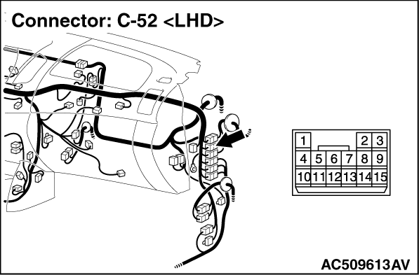
Prior to the wiring harness inspection, check intermediate connector C-52 <L.H. drive vehicles> or C-34 <R.H. drive vehicles>, and repair if necessary.
|
- Check the power supply line for open circuit.
Q.
Are the wiring harness between engine control relay connector A-20X (terminal 3) and immobilizer-ECU connector C-142 (terminal 1) in good condition?
Go to Step 5.
Repair the wiring harness.
|
|
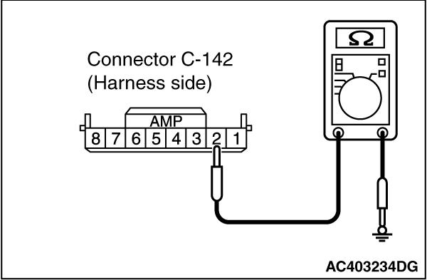
(1)Disconnect the immobilizer-ECU connector C-142 and measure the resistance at immobilizer-ECU connector C-142 harness side.
(2)Turn the ignition switch to “ON” position.
|
|
(3)Measure the resistance between terminal 2 and earth.
OK: Continuity exists (2 Ω or less)
Q.
Is the check result normal?
The procedure is complete.
Go to Step 6.
|


|
| note |
Prior to the wiring harness inspection, check joint connector C-120, and repair if necessary.
|
- Check the earth wires for open circuit.
Q.
Are the wiring harness between immobilizer-ECU connector C-142 (terminal 2) and earth in good condition?
The procedure is complete.
Repair the wiring harness.
|