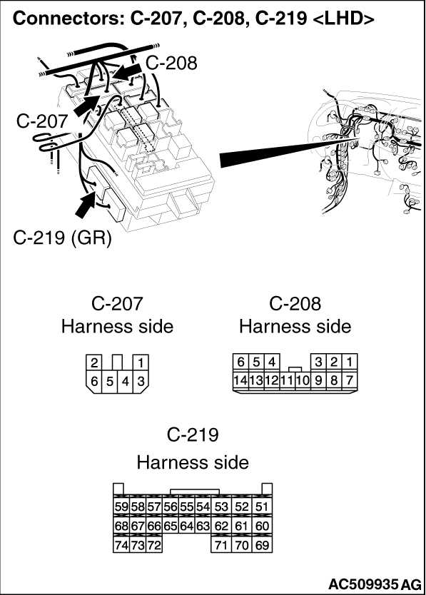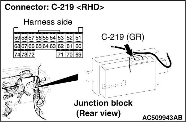
|
Q.
Is the check result normal?
 Go to Step 2. Go to Step 2.
 Repair the defective connector. Repair the defective connector.
|
|
(1)Disconnect the connector, and measure at the wiring harness side.
(2)Turn the ignition switch to the "ACC" position.
|

|
(3)Voltage between C-219 ETACS-ECU connector terminal No.74 and body earth
OK: System voltage
Q.
Is the check result normal?
Go to Step 4.
Go to Step 3.
|


|
| note |
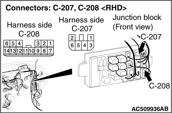
Prior to the wiring harness inspection, check joint connector C-127, junction block connectors
C-207 and C-208, and repair if necessary.
|
- Check the power supply line for open circuit.
Q.
Is the check result normal?
The trouble can be an intermittent malfunction (Refer to GROUP 00 -
How
to use Troubleshooting/inspection Service Points -
How to Cope with Intermittent
Malfunction  ). ).
Repair the wiring harness.
|
|
|
Check the input signals from the ignition switch (ACC).
|
|
|
- Turn the ignition switch to the "ACC" position.
|
|
|
OK: Normal condition is displayed.
|
|
|
Q.
Is the check result normal?
|
|
|
The trouble can be an intermittent malfunction (Refer to GROUP 00 -
How
to use Troubleshooting/inspection Service Points -
How to Cope with Intermittent
Malfunction ).
|
|
|
|