
|
1.Type A (projected dimensions)
- Indicates the dimension when a measurement location is projected
onto the plane.
- The difference in height of the measurement points should be taken into consideration
when measuring.
- The height indicates a distance from the assumed standard line established 200 mm
below the lowest measurement point.
|

|
2.Type B (actual-measurement dimensions)
- Indicates the actual distance between the measurement points.
- Measure using a tracking gauge or a measuring tape, etc.
| note |
- Make the lengths of the tracking gauge probes the same (A=A’).
- Do not bend or twist the measuring tape.
|
|

|
3.Insert the tracking gauge probes securely into the measurement holes.
4.When the standard dimensions in the illustration are enclosed by rectangle, this indicates
that the symmetrical left and right positions have the same dimensions.
|

|
5.When using a notch for dimension measurement, set the measuring point at the centre of
the notch.
|
|
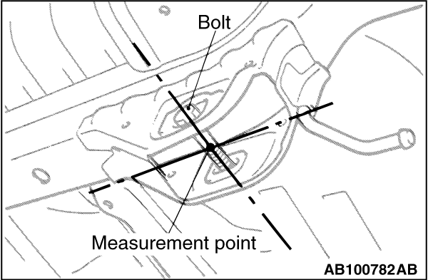
6.When measuring the suspension mounting arm, or link mounting position, use the suspension
mounting bolt, etc. (Type B only)
7.The body centre points are shown for the purpose of checking the position of the left
and right symmetry location.
|