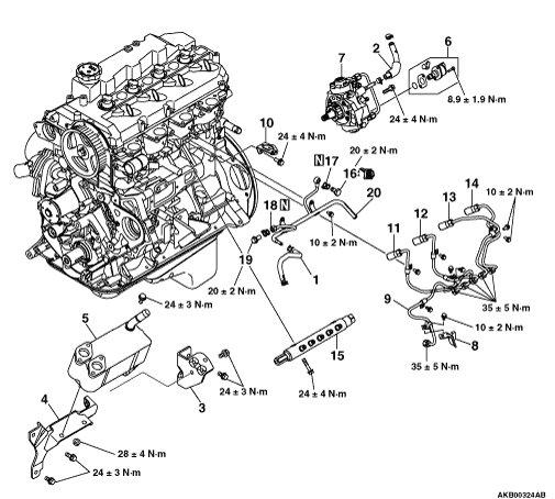
REMOVAL AND INSTALLATION


<Except Euro5b>


Removal steps


1.
Fuel return hose


2.
Fuel inlet hose

>>B<<
3.
EGR cooler bracket


4.
EGR cooler

>>B<<
5.
Suction control valve kit *1

>>B<<
6.
Supply pump


7.
Fuel supply pump pipe bracket

>>B<<
8.
Fuel supply pump pipe

>>A<<
9.
Fuel injection No.1 pipe

>>A<<
10.
Fuel injection No.2 pipe

>>A<<
11.
Fuel injection No.3 pipe

>>A<<
12.
Fuel injection No.4 pipe

>>A<<
13.
Common rail

>>A<<
14.
Eye bolt (Cylinder head side)

>>A<<
15.
Fuel return gasket

>>A<<
16.
Eye bolt (Common rail side)

>>A<<
17.
Fuel return gasket

>>A<<
18.
Fuel return pipe
caution *1: Unless replaced, do not remove the sensor.


<Euro5b>


Removal steps


1.
Fuel return hose


2.
Fuel inlet hose

>>B<<
3.
EGR cooler bracket assembly "B"

>>B<<
4.
EGR cooler bracket assembly "A"

>>B<<
5.
EGR cooler


6.
Suction control valve kit *1

>>B<<
7.
Supply pump

>>B<<
8.
Fuel supply pump pipe bracket

>>A<<
9.
Fuel supply pump pipe

>>A<<
10.
Bracket


11.
Fuel injection No.1 pipe

>>A<<
12.
Fuel injection No.2 pipe

>>A<<
13.
Fuel injection No.3 pipe

>>A<<
14.
Fuel injection No.4 pipe

>>A<<
15.
Common rail

>>A<<
16.
Eye bolt (Cylinder head side)

>>A<<
17.
Fuel return gasket

>>A<<
18.
Eye bolt (Common rail side)

>>A<<
19.
Fuel return gasket

>>A<<
20.
Fuel return pipe
caution *1: Unless replaced, do not remove the sensor.

INSTALLATION SERVICE POINTS


>>A<< BRACKET / FUEL INJECTION PIPE / COMMON RAIL / EYE BOLT / FUEL RETURN GASKET / FUEL RETURN PIPE INSTALLATION


caution
  • The reinstallation histories of the removed injection pipe are up to five times. To count how many times the injection pipe is reinstalled, record the number of the reinstallation histories on the service booklet by adding this latest number of the histories, which is usually "1", to the previous one. Use a new injection pipe when the total reinstallation history numbers reach five times, or when the injector or common rail is replaced. In this case, record "a new injection pipe, the number of the reinstallation histories is zero" on the service booklet.
  • If a fuel leak is present in the fuel injection pipe and fuel injection pipe set once, do not reuse it and replace with a new one.
  • If the fuel injector assembly, common rail assembly or supply pump assembly is replaced, the contact surface (seal surface) between the fuel injection pipe and fuel injection pipe set, and the other side component is changed, do not reuse the fuel injection pipe and fuel supply pump pipe and replace with a new one.
  • When the injection pipe is reinstalled, confirm there is no foreign material on the seal surface or in the pipe and then install it not to deviate from the axis, fitting the seal surface.

1.Temporarily tighten the fuel return pipe with bolts.

2.Slightly put the hatched area of the bracket to the cylinder port and tighten it to the specified torque of 24 ± 4 N·m. <Euro5b>
3.Tighten to the specified torque of 20 ± 2 N·m the eye bolt and the fuel return gasket located at the cylinder head side.

4.Temporarily tighten the common rail with bolts, holding the common rail body.
note At this time, do not hold the pressure limiter or pressure sensor of the common rail.
note Before the installation, confirm there is neither foreign material nor a rust on the threads and the sealing surface of a high-pressure pipe.
5.Align the fuel injection pipe centre axis with the other side components (fuel injector assembly and common rail assembly) centre axis to install the fuel injection pipe. Then, tighten the flare nut temporarily until the tip of pipe (seal surface) contacts with the other side components.
note When the fuel injection pipe is installed, tighten the flare nut while shaking the pipe lightly to align the centre axis of both components.

6.Using special tool Fuel injection pipe wrench (MB992188), install injection pipe assembly No.1 to No.4.
Tighten to the specified torque of 35 ± 5 N·m the flare nuts of the fuel injection pipe No.1 to No.4 at injector side.

7.Using special tool Fuel injection pipe wrench (MB992188), install injection pipe assembly No.1 to No.4.
Tighten to the specified torque of 35 ± 5 N·m the flare nuts of the fuel injection pipe No.1 to No.4 at common rail side.
8.Tighten the common rail to the specified torque of 24 ± 4 N·m.
9.Tighten to the specified torque of 20 ± 2 N·m the eye bolt and the fuel return gasket located at the common rail side.
10.Tighten the fuel return pipe to the specified torque of 10 ± 2 N·m.
11.Tighten to the specified torque of 10 ± 2 N·m the bolts of the fuel injection pipe No.1 to No.4.

>>B<< EGR COOLER / EGR COOLER BRACKET / SUPPLY PUMP / FUEL SUPPLY PUMP PIPE / FUEL SUPPLY PUMP PIPE BRACKET INSTALLATION


caution
  • The reinstallation histories of the removed fuel supply pump pipe are up to five times. To count how many times the fuel supply pump pipe is reinstalled, record the number of the reinstallation histories on the service booklet by adding this latest number of the histories, which is usually "1", to the previous one. Use a new fuel supply pump pipe when the total reinstallation history numbers reach five times, or when the supply pump or common rail is replaced. In this case, record "a new fuel supply pump pipe, the number of the reinstallation histories is zero" on the service booklet.
  • If a fuel leak is present in the fuel injection pipe and fuel injection pipe set once, do not reuse it and replace with a new one.
  • If the fuel injector assembly, common rail assembly or supply pump assembly is replaced, the contact surface (seal surface) between the fuel injection pipe and fuel injection pipe set, and the other side component is changed, do not reuse the fuel injection pipe and fuel supply pump pipe and replace with a new one.
  • When the fuel supply pump pipe is reinstalled, confirm there is no foreign material on the seal surface or in the pipe and then install it not to deviate from the axis, fitting the seal surface.
1.Align the fuel supply pump pipe centre axis with the other side components (common rail assembly and supply pump assembly) centre axis to install the fuel supply pump pipe. Then, tighten the flare nut temporarily until the tip of pipe (seal surface) contacts with the other side components.
note When the fuel supply pump pipe is installed, tighten the flare nut while shaking the pipe lightly to align the centre axis of both components.
2.Temporarily tighten the supply pump with bolts.
3.Temporarily tighten the fuel supply pump pipe flare nuts.
4.Tighten to the specified torque of 35 ± 5 N·m the flare nuts of the fuel supply pump pipe together with the supply pump and common rail.
5.Tighten the supply pump to the specified torque of 24 ± 4 N·m.


6.Tighten the EGR cooler to the specified torque of 24 ± 3 N·m.
note The arrow position shown in the illustration is tightened together with the fuel supply pump pipe bracket.

7.Tighten the EGR cooler bracket to the specified torque of 24 ± 3 N·m.
8.Tighten to the specified torque of 10 ± 2 N·m the installation fuel supply pump pipe bolts together with the fuel supply pump pipe bracket.