Code No. U1117 ETACS-ECU (Immobilizer-ECU) Time-out
| caution | If Diagnosis Code U1117 is output from engine-ECU surely perform CAN bus line diagnosis. |
| caution | Replace ECU after certainly confirming that the communication circuits are normal. |
| note | When the diagnosis codes relating to the CAN communication error are set, make sure of the vehicle equipment. When the vehicle is not equipped with the system the engine-ECU communicates to, the diagnosis code is always set. This is not abnormal. |
TROUBLE JUDGMENT
Check Condition
- Ignition switch is in "ON" position.
- The signal from the ETACS-ECU is not received for 0.5 second or more.
COMMENT ON TROUBLE SYMPTOM
Current malfunction
- The failure is possibly caused by malfunction of the harness and connector in CAN bus line between engine-ECU and ETACS-ECU, by malfunction in the power supply system of ETACS-ECU, in ETACS-ECU itself, in engine-ECU.
- Focus on diagnosing malfunction of the harness and connector in CAN bus line between engine-ECU and ETACS-ECU as well as malfunction in the power supply system of ETACS-ECU (Refer to GROUP 00 - How to Use Troubleshooting/Inspection Service Points - How to Cope with Intermittent Malfunctions
 ).
).
| caution | 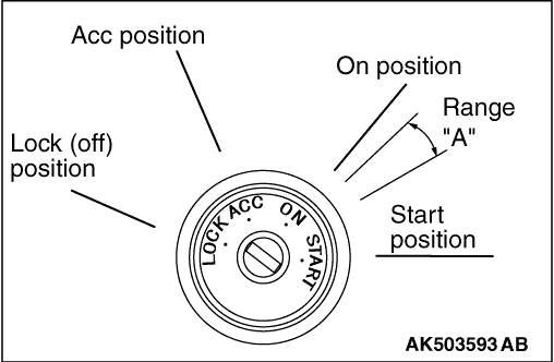 When the ignition key is maintained within the range "A" (i.e., the ignition switch IG2 is in OFF position but the cranking does not start) for more than 1 second, engine-ECU stores diagnosis code U1117 (the past trouble). |
| note | In case of Past trouble, M.U.T.-III CAN bus diagnosis cannot detect the failure even if there is malfunction in CAN bus, so that check CAN bus line in the same way as Intermittent malfunction (Refer to GROUP 00 - How to Use Troubleshooting/Inspection Service Points - How to Cope with Intermittent Malfunctions ). The diagnosis codes being set to each ECU with CAN communication can narrow down the most suspected area. (Refer to GROUP 54C - Explanation About The M.U.T.-III Can Bus Diagnostics ). |
PROBABLE CAUSE
- Failed of the harness and the connector
- Failed engine-ECU
- Failed ETACS-ECU
DIAGNOSIS PROCEDURE |
STEP 1. M.U.T.-III CAN bus diagnostics |
|
Q.
Is the check result normal?
|
 Go to Step 2. Go to Step 2. |
|
 Correct CAN bus line (Refer to GROUP 54C - Diagnosis - Can Bus Diagnostic Chart ), and then go to Step 3. Correct CAN bus line (Refer to GROUP 54C - Diagnosis - Can Bus Diagnostic Chart ), and then go to Step 3. |
|
STEP 2. M.U.T.-III other system diagnosis codes |
|
Q.
Is the diagnosis code set?
|
| YES : Perform the troubleshooting of immobilizer system (Refer to GROUP 54A - Immobilizer System - Check Chart for Diagnosis Code ). |
|
| Go to Step 3. |
|
STEP 3. M.U.T.-III diagnosis code |
|
Q.
Is the diagnosis code set?
|
| Replace the engine-ECU. When the engine-ECU is replaced, write the chassis number (Refer to GROUP 00 - Precautions Before Service - How to Perform Chassis Number Writing ). After replacing the engine-ECU, register the injector identification code and learn fuel injection (Refer to GROUP 00 - Precautions Before Service - What The Common Rail Engine Learns ). After registering the injector identification code, the vehicle equipped with the DPF carries out the forcible DPF regeneration. (Refer to GROUP 17 - Emission Control - Diesel Particulate Filter (DPF) System - Forcible DPF Regeneration ). |
|
| Intermittent malfunction in CAN bus line between engine-ECU and ETACS-ECU (Refer to GROUP 00 - How to Use Troubleshooting/Inspection Service Points - How to Cope with Intermittent Malfunction ). |
|