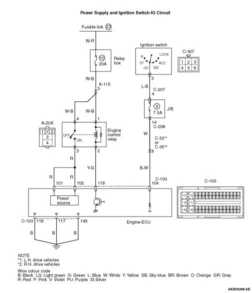
|
|
- Measure battery voltage during cranking.
|
|
|
Q.
Is the check result normal?
|
|
|
 Check battery (Refer to GROUP 54A - Battery - On-vehicle Service - Battery test Check battery (Refer to GROUP 54A - Battery - On-vehicle Service - Battery test  ). ).
|
|
|
|
|
|
- Check engine control relay itself (Refer to ).
|
|
|
Q.
Is the check result normal?
|
|
|
Replace the engine control relay.
|
|
|
|

|
Q.
Is the check result normal?
 Go to Step 4. Go to Step 4.
Repair or replace.
|
|
- Remove relay, and measure at harness side.
- Voltage between terminal No. 1 and earth, also between terminal No. 4 and earth.
OK: System voltage
Q.
Is the check result normal?
Go to Step 5.
Check intermediate connector A-115, and repair if necessary. If intermediate connector is normal, check and repair harness between A-20X (terminal No. 1 and terminal No. 4) engine control relay connector and battery.
|

|
Q.
Is the check result normal?
Go to Step 6.
Repair or replace.
|
|
- Disconnect connector, and measure at harness side.
- Voltage between terminal No. 118 and earth.
OK: System voltage
Q.
Is the check result normal?
Go to Step 7.
Repair the harness wire.
|
|
- Disconnect connector, and measure at harness side.
- Short-circuit terminal No. 118 to earth.
- Voltage between terminal No. 101 and earth also between terminal No. 102 and earth.
OK: System voltage
Q.
Is the check result normal?
Go to Step 8.
Repair the harness wire.
|
|
- Disconnect connector, and measure at harness side.
- Check open circuit between terminal No. 145 and earth.
Q.
Is the check result normal?
Go to Step 9.
Repair the harness wire.
|
|
Q.
Is the check result normal?
Go to Step 10.
Repair or replace.
|
|
- Disconnect connector.
- Check open circuit between terminal No. 116 and earth also between terminal No. 117 and earth.
Q.
Is the check result normal?
Go to Step 11.
Repair the harness wire.
|
|
- Disconnect connector, and measure at harness side.
- Ignition switch: ON
- Voltage between terminal No. 104 and earth.
OK: System voltage
Q.
Is the check result normal?
Go to Step 12.
Check intermediate connector C-53 <L. H. drive vehicles> or C-35 <R. H. drive vehicles>, and repair if necessary. If intermediate connector is normal, check and repair harness between C-103 (terminal No. 104) engine-ECU connector and C-208 J/B connector.
|
|
|
Q.
Does trouble symptom persist?
|
|
|
Replace the engine-ECU. When the engine-ECU is replaced, write the chassis number (Refer to GROUP 00 - Precautions Before Service - How to Perform Chassis Number Writing ). After replacing the engine-ECU, register the injector identification code and learn fuel injection (Refer to GROUP 00 - Precautions Before Service - What The Common Rail Engine Learns ). After registering the injector identification code, the vehicle equipped with the DPF carries out the forcible DPF regeneration. (Refer to GROUP 17 - Emission Control - Diesel Particulate Filter (DPF) System - Forcible DPF Regeneration ).
|
|
|
|
|
|
Intermittent malfunction (Refer to GROUP 00 - How to Use Troubleshooting/Inspection Service Points - How to Cope with Intermittent Malfunction ).
|
|
|
|