|
|
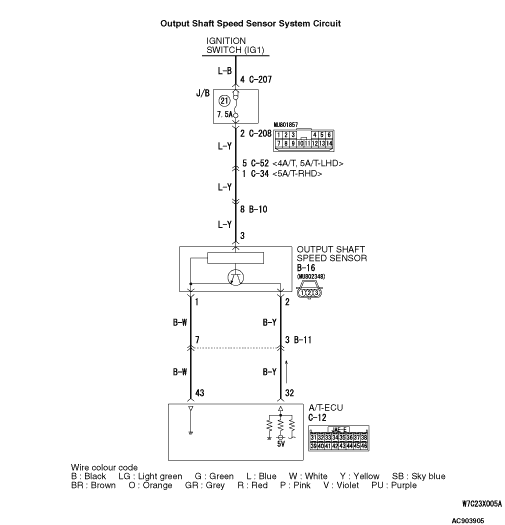
Item 06: Output shaft speed sensor (Refer to data list reference table  ). ).
|
|
|
Q.
Is the check result normal?
|
|
|
 Intermittent malfunction (Refer to GROUP 00 -
How to Cope with Intermittent
Malfunction ). Intermittent malfunction (Refer to GROUP 00 -
How to Cope with Intermittent
Malfunction ).
|
|
|
|
|
|
Check for the contact with terminals.
|
|
|
Q.
Is the check result normal?
|
|
|
 Repair the defective connector. Repair the defective connector.
|
|
|
|
|
|
Disconnect the connector, and measure the resistance between terminal 1 and earth at the
wiring harness side.
|
|
|
OK: Continuity (Less than 2 Ω)
|
|
|
Q.
Is the check result normal?
|
|
|
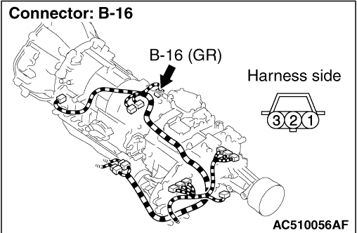
(1)Connect output shaft speed sensor connector B-16.
|
|
|
(2)Turn the ignition switch to the "ON" position.
|
|
|
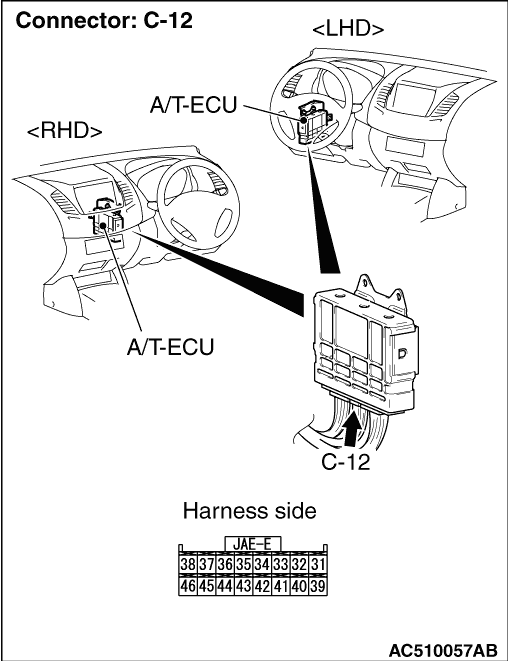
(3)Measure the voltage between A/T-ECU connector C-12 terminal No.43 and
earth.
OK: 0.5 V or less
|
|
|
Q.
Is the check result normal?
|
|
|
Check for the contact with terminals.
|
|
|
Q.
Is the check result normal?
|
|
|
Repair the defective connector.
|
|
|
|
|
|
Item 06: Output shaft speed sensor (Refer to data list reference table ).
|
|
|
Q.
Is the check result normal?
|
|
|
Intermittent malfunction (Refer to GROUP 00 -
How to Cope with Intermittent
Malfunction ).
|
|
|
|
|
|
Check for the contact with terminals.
|
|
|
Q.
Is the check result normal?
|
|
|
Repair the defective connector.
|
|
|
|
|
|
Check the earth line for open circuit.
|
|
|
Q.
Is the check result normal?
|
|
|
Repair the wiring harness.
|
|
|
|
|
|
(1)Disconnect the connector, and measure the voltage between terminal 3 and earth
at the wiring harness side.
|
|
|
(2)Turn the ignition switch to the ON position.
OK: System voltage
|
|
|
Q.
Is the check result normal?
|
|
|
Check for the contact with terminals.
|
|
|
Q.
Is the check result normal?
|
|
|
Repair the defective connector.
|
|
|
|
|
|
Check the power supply line for short or open circuit.
|
|
|
Q.
Is the check result normal?
|
|
|
Repair the wiring harness.
|
|
|
|
|
|
(1)Disconnect the connector, and measure the voltage between terminal 2 and earth
at the wiring harness side.
|
|
|
(2)Turn the ignition switch to the ON position.
OK: 4.5 -
4.9 V
|
|
|
Q.
Is the check result normal?
|
|
|
(1)Disconnect output shaft speed sensor connector B-16.
|
|
|
(2)Turn the ignition switch to the "ON" position.
|
|
|
(3)Measure the voltage between A/T-ECU connector C-12 terminal No.32 and
earth.
OK: 4.5 -
4.9 V
|
|
|
Q.
Is the check result normal?
|
|
|
Check for the contact with terminals.
|
|
|
Q.
Is the check result normal?
|
|
|
Repair the defective connector.
|
|
|
|
|
|
Check the output line for short circuit.
|
|
|
Q.
Is the check result normal?
|
|
|
Repair the wiring harness.
|
|
|
|
|
|
Check for the contact with terminals.
|
|
|
Q.
Is the check result normal?
|
|
|
Repair the defective connector.
|
|
|
|
|
|
Check the output line for open circuit.
|
|
|
Q.
Is the check result normal?
|
|
|
Repair the wiring harness.
|
|
|
|
|
|
(1)Shift the selector lever to the D range.
|
|
|
(2)Accelerate the vehicle to approximately 50 km/h (shift range;
3rd.)
|
|
|
(3)Connect an oscilloscope, and measure the voltage between A/T-ECU connector
C-12 terminal No.32 and earth.
OK: A wave pattern such as the one shown on (Check
Procedure Using an Oscilloscope) should be output, and the maximum value should be 4.8 V or
more and the minimum value should be 0.8 V or less. There should be no noise in the output wave
pattern.
|
|
|
Q.
Is the check result normal?
|
|
|
Check for the contact with terminals.
|
|
|
Q.
Is the check result normal?
|
|
|
Repair the defective connector.
|
|
|
|
|
|
(1)Replace the output shaft speed sensor.
|
|
|
(2)Test drive the vehicle.
|
|
|
(3)Check if the diagnosis code is set.
|
|
|
Q.
Is diagnosis code P1767 set?
|
|
|
The inspection is complete.
|
|
|
|
|
|
Visually check the output shaft <4A/T>
or direct planetary carrier <5A/T>
for
damage.
|
|
|
Q.
Is the check result normal?
|
|
|
Eliminate the cause of the noise.
|
|
|
|
|
|
Replace the output shaft <4A/T>
or direct planetary carrier <5A/T>.
|
|
|
|