|
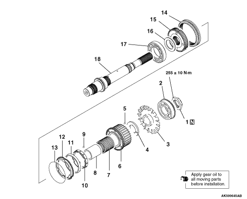
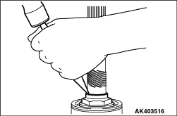
1.Remove the lock nut from the shaft.
|
|
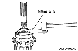
2.Hold the drive sprocket in a soft-jaw vise.
3.Shift the clutch sleeve to the drive sprocket side.
4.Use special tool Power steering lock nut special spanner (MB991013) to remove the
lock nut.
|

|
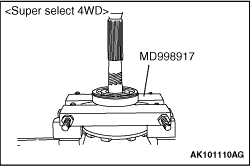
1.Use special tool to support the ball bearing.
- Bearing remover (MD998801) <Easy select 4WD>
- Bearing remover (MD998817) <Super select 4WD>
2.Use a press to push at a rear end of the rear output shaft, and then remove the radial
ball bearing.
| note |
The bearing may fit loosely on the shaft, so that removal is possible without using a press.
|
|

|
1.Place special tool Bearing remover (MD998801) so that the load is applied at the bearing.
2.Use a press to push at the rear end of the rear output shaft, and then remove the
clutch hub and ball bearing.
| note |
The clutch hub may fit loosely on the shaft, so that removal is possible without using
a press.
|
|


|
1.Fit the ball bearing and stopper plate onto the rear output shaft.
2.Use special tools to press in the ball bearing.
- Bearing remover (MD998801) <Easy select 4WD>
- Installer cap (MD998812)
- Installer-100 (MD998813) <Easy select 4WD>
- Installer-200 (MD998814)
- Installer adapter (MD998823) <Super select 4WD>
- Installer adapter (MD998829) <Easy select 4WD>
|

|
1.Install the thickest snap ring that can be fitted in the snap ring groove of the rear
output shaft.
2.Make sure that the rear output shaft bearing end play meets the standard value.
Standard value: 0 - 0.08 mm
(For rear output shaft end play)
|

|
1.Confirm the clutch hub installation direction, and fit onto the rear output shaft.
2.Use special tools press in the clutch hub.
- Bearing remover (MD998801)
- Installer cap (MD998812)
- Installer-100 (MD998813)
- Installer-200 (MD998814)
- Installer adapter (MD998821)
| note |
The clutch hub may fit loosely on the shaft, so that installation is possible without
using a press.
|
|
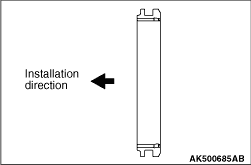
|
Check that the clutch sleeve is in the correct direction for installation.
|

|
1.Use special tools to install the radial ball bearing.
- Bearing remover (MD998801)
- Installer cap (MD998812)
- Installer-200 (MD998814)
- Installer adapter (MD998821)
| note |
The ball bearing may be fitted loosely on the shaft, so that installation is possible
without using a press
|
|
|
1.Hold the drive sprocket in a soft-jaws vise.
2.Shift the clutch sleeve to the drive sprocket side.
3.Using special tool Power steering lock nut special spanner (MB991013) tighten the
lock nut to the specified torque 255 ± 10 N·m.
|
|
4.Stake the two places of the lock nut as shown in illustration.
|