|
|
Use M.U.T.-III to diagnose the CAN bus lines.
|
|
|
Q.
Is the check result normal?
|
|
|
 Repair the CAN bus lines (Refer to GROUP 54C, CAN Bus Diagnostics Table Repair the CAN bus lines (Refer to GROUP 54C, CAN Bus Diagnostics Table  .). Then go to Step 6. .). Then go to Step 6.
|
|
|
|
|
|
Q.
Is the check result normal?
|
|
|
Repair or replace it. Then go to Step 6.
|
|
|
|
|
|
(1)Disconnect the A-01 ABS-ECU connector and C-113 combination meter connector.
|
|
|
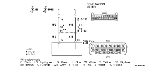
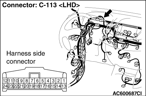
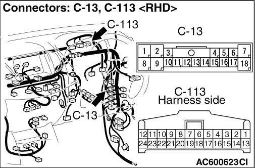
(2)Resistance between the C-113 combination meter connector terminal No.19 and the body earth.
OK: No continuity
|
|
|
Q.
Is the check result normal?
|
|
|
A short circuit may be present in the earth circuit. Repair the wiring harness between the A-01 ABS-ECU terminal No.16 and the C-113 combination meter connector terminal No.19. Then go to Step 6.
|
|
|
|
|
|
Q.
Is any diagnosis code set?
|
|
|
 Refer to Diagnosis Code Chart (Refer to .). Then go to Step 6. Refer to Diagnosis Code Chart (Refer to .). Then go to Step 6.
|
|
|
|
|
|
Replace the combination meter assembly (Refer to GROUP 54A, Combination Meter Assembly .). Then go to Step 5.
|
|
|
|
|
|
Q.
Turn the ignition switch to the "ON" position. Does the ABS warning lamp illuminate for three seconds, and then go out after the engine starts?
|
|
|
The procedure is complete.
|
|
|
|
|
|
Replace the hydraulic unit (integrated with ABS-ECU) (Refer to .). Then go to Step 6.
|
|
|
|
|
|
Q.
Turn the ignition switch to the "ON" position. Does the ABS warning lamp illuminate for three seconds, and then go out after the engine starts?
|
|
|
The procedure is complete.
|
|
|
|