|
|
Use M.U.T.-III to diagnose the CAN bus lines.
|
|
|
Q.
Is the check result normal?
|
|
|
 Repair the CAN bus lines (Refer to GROUP 54C - CAN Bus Diagnostics Table Repair the CAN bus lines (Refer to GROUP 54C - CAN Bus Diagnostics Table  .).
On completion, go to Step 2. .).
On completion, go to Step 2.
|
|
|
|
|
|
(1)Erase the diagnosis code.
|
|
|
(2)Drive the vehicle at 15 km/h or more.
| note |
The ABS warning lamp does not turn OFF in some cases unless the vehicle runs at 15 km/h
or higher.
|
|
|
|
Q.
Are diagnosis codes No.C1201, C1206, C1211 or C1216 set?
|
|
|
This diagnosis is complete.
|
|
|
|
|
|
Check that diagnosis codes No.C1200, C1202, C1205, C1207, C1210, C1212, C1215 or C1217
is also set.
|
|
|
Q.
Are diagnosis codes No.C1200, C1202, C1205, C1207, C1210, C1212, C1215 or C1217 also
set?
|
|
|
 Perform the diagnosis for diagnosis codes No.C1200, C1202, C1205, C1207, C1210,
C1212, C1215 or C1217 (Refer to , .). Perform the diagnosis for diagnosis codes No.C1200, C1202, C1205, C1207, C1210,
C1212, C1215 or C1217 (Refer to , .).
|
|
|
|
|
|
Check the following data list (Refer to .).
|
|
|
- Item No.01: FL wheel speed sensor
- Item No.02: FR wheel speed sensor
- Item No.03: RL wheel speed sensor
- Item No.04: RR wheel speed sensor
|
|
|
Q.
Is the check result normal?
|
|
|
Check how the wheel speed sensor is installed correctly (Disconnection of wheel speed
sensor, loose mounting bolt, etc.).
|
|
|
- Code No.C1201 is set: Wheel speed sensor (FR)
- Code No.C1206 is set: Wheel speed sensor (FL)
- Code No.C1211 is set: Wheel speed sensor (RR)
- Code No.C1216 is set: Wheel speed sensor (RL)
|
|
|
Q.
Is the check result normal?
|
|
|
Reinstall the wheel speed sensor correctly (Refer to .).
Then go to Step 13.
|
|
|
|
|
|
- Code No.C1201 is check: Wheel speed sensor (FR)
- Code No.C1206 is check: Wheel speed sensor (FL)
- Code No.C1211 is check: Wheel speed sensor (RR)
- Code No.C1216 is check: Wheel speed sensor (RL)
|
|
|
Q.
Is the check result normal?
|
|
|
Replace the wheel speed sensor (Refer to .). Then
go to Step 13.
|
|
|
|
|
|
Q.
Is the check result normal?
|
|
|
NO (wheel bearing axial play is not within the standard value) <2WD (Except High
rider)> : Replace the wheel bearing (Refer to GROUP 26 - Front axle hub assembly .).
Then go to Step 13. : Replace the wheel bearing (Refer to GROUP 26 - Front axle hub assembly .).
Then go to Step 13.
|
|
|
|
|
|
NO (wheel bearing axial play is not within the standard value) <2WD (High rider),
4WD> : Replace the front hub assembly (Refer to GROUP 26 - Front axle hub assembly .).
Then go to Step 13.
|
|
|
|
|
|
NO (rear wheel bearing axial play is not within the standard value) : Replace the rear axle shaft bearing (Refer to GROUP 27 - Axle shaft assembly .). Then
go to Step 13.
|
|
|
|
|
|
Check the ABS rotor, which diagnosis code indicates, for foreign material or deformation.
|
|
|
Q.
Is the check result normal?
|
|
|
NO <ABS rotor (FR, FL) abnormal> <2WD (Except High rider)> : If the ABS rotor is contaminated with foreign material, clean it. If the wheel
bearing is deformed, replace it (Refer to GROUP 26 - Front axle hub assembly .).
Then go to Step 13.
|
|
|
|
|
|
NO <ABS rotor (FR, FL) abnormal> <2WD (High rider), 4WD> : If the ABS rotor is contaminated with foreign material, clean it. If the front
hub assembly is deformed, replace it (Refer to GROUP 26 - Front axle hub assembly .).
Then go to Step 13.
|
|
|
|
|
|
NO <ABS rotor (RR, RL) abnormal> : If the ABS rotor is contaminated with foreign material, clean it. If the rear axle
shaft bearing is deformed, replace it (Refer to GROUP 27 - Axle shaft assembly .).
Then go to Step 13.
|
|
|
|
|
|
Q.
Is the check result normal?
|
|
|
Repair the defective connector. Then go to Step 13.
|
|
|
|
|
|
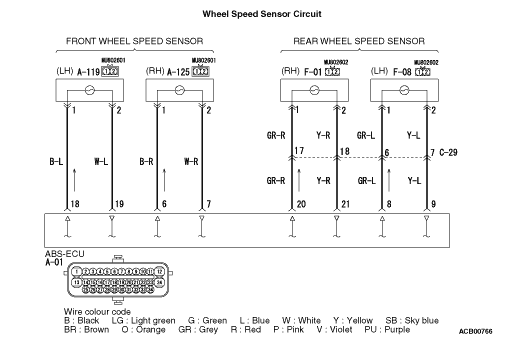
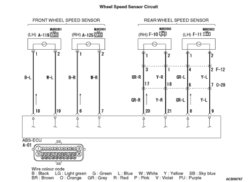
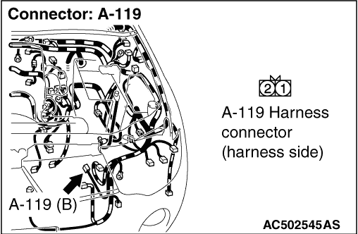
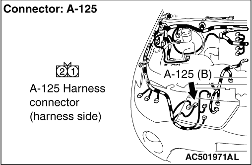
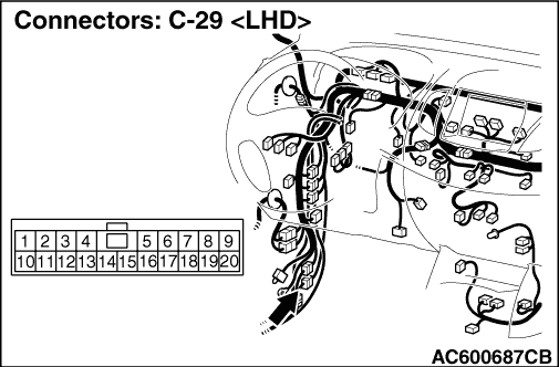
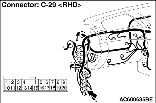
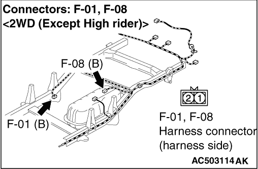
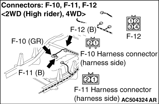
(1)Disconnect the A-01 ABS-ECU connector, A-125 front wheel speed sensor (RH) connector <C1201>,
A-119 front wheel speed sensor (LH) connector <C1206>, F-01 rear wheel speed
sensor (RH) connector <C1211, 2WD (Except High rider)> or F-10 rear wheel
speed sensor (RH) connector <C1211, 2WD (High rider), 4WD>, F-08 rear wheel
speed sensor (LH) connector <C1216, 2WD (Except High rider)> or F-11 rear
wheel speed sensor (LH) connector <C1216, 2WD (High rider), 4WD>.
|
|
|
(2)Turn the ignition switch to the "ON" position.
|
|
|
(3)Measure the voltage between the A-01 ABS-ECU connector terminals.
Code No.C1200 is set
- Between terminal No.7 and body earth
Code No.C1205 is set
- Between terminal No.19 and body earth
Code No.C1210 is set
- Between terminal No.21 and body earth
Code No.C1215 is set
- Between terminal No.9 and body earth
OK: 1 V or less
|
|
|
Q.
Is the check result normal?
|
|
|
Repair the wiring harness. Then go to Step 13.
|
|
|
|
|
|
(1)Disconnect the A-01 ABS-ECU connector, A-125 front wheel speed sensor (RH) connector <C1201>,
A-119 front wheel speed sensor (LH) connector <C1206>, F-01 rear wheel speed
sensor (RH) connector <C1211, 2WD (Except High rider)> or F-10 rear wheel
speed sensor (RH) connector <C1211, 2WD (High rider), 4WD>, F-08 rear wheel
speed sensor (LH) connector <C1216, 2WD (Except High rider)> or F-11 rear
wheel speed sensor (LH) connector <C1216, 2WD (High rider), 4WD>.
|
|
|
(2)Measure the resistance between the A-01 ABS-ECU connector terminals.
Code No.C1200 is set
- Between terminal No.7 and body earth
Code No.C1205 is set
- Between terminal No.9 and body earth
Code No.C1210 is set
- Between terminal No.21 and body earth
Code No.C1215 is set
- Between terminal No.9 and body earth
OK: No continuity
|
|
|
Q.
Is the check result normal?
|
|
|
Repair the wiring harness. Then go to Step 13.
|
|
|
|
|
|
(1)Erase the diagnosis code.
|
|
|
(2)Drive the vehicle at 15 km/h or more.
| note |
The ABS warning lamp does not turn OFF in some cases unless the vehicle runs at 15 km/h
or higher.
|
|
|
|
Q.
Are diagnosis codes No.C1201, C1206, C1211 or C1216 set?
|
|
|
Replace the hydraulic unit (integrated with ABS-ECU) (Refer to .).
Then go to Step 13.
|
|
|
|
|
|
Intermittent malfunction (Refer to GROUP 00 - How to Cope with Intermittent
Malfunctions .).
|
|
|
|
|
|
(1)Erase the diagnosis code.
|
|
|
(2)Drive the vehicle at 15 km/h or more.
| note |
The ABS warning lamp does not turn OFF in some cases unless the vehicle runs at 15 km/h
or higher.
|
|
|
|
Q.
Are diagnosis codes No.C1201, C1206, C1211 or C1216 set?
|
|
|
This diagnosis is complete.
|
|
|
|