|
|
Use M.U.T.-III to diagnose the CAN bus lines.
|
|
|
Q.
Is the check result normal?
|
|
|
 Repair the CAN bus lines (Refer to GROUP 54C - CAN Bus Diagnostics Table Repair the CAN bus lines (Refer to GROUP 54C - CAN Bus Diagnostics Table  .). Then go to Step 2. .). Then go to Step 2.
|
|
|
|
|
|
(1)Erase the diagnosis code.
|
|
|
(2)Turn the ignition switch to the "LOCK" (OFF) position.
|
|
|
(3)Turn the ignition switch to the "ON" position.
|
|
|
(4)Check if the diagnosis code is set.
|
|
|
Q.
Is diagnosis code No.C1861 set?
|
|
|
This diagnosis is complete.
|
|
|
|
|
|
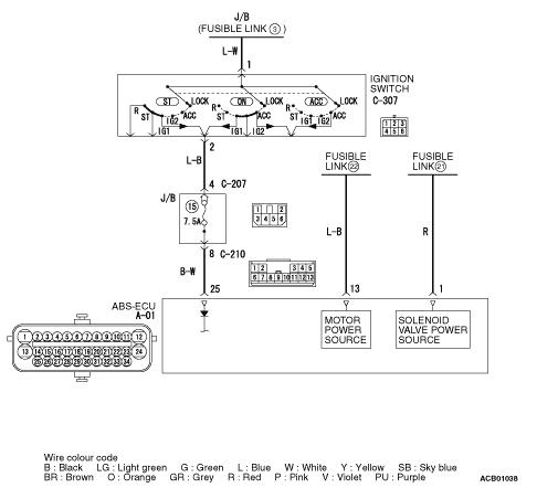
Visually check for open circuit in the fusible link No.21, No.22 or the fuse No.15.
|
|
|
Q.
Is the check result normal?
|
|
|
Replace the fusible link or fuse. Then go to Step 10.
|
|
|
|
|
|
Refer to GROUP 54A - Battery Test .
|
|
|
Q.
Is the battery in good condition?
|
|
|
Charge or replace the battery. Then go to Step 10.
|
|
|
|
|
|
Refer to GROUP 16 - Charging System .
|
|
|
Q.
Is the charging system in good condition?
|
|
|
Repair or replace the charging system component(s). Then go to Step 10.
|
|
|
|
|
|
Q.
Is the check result normal?
|
|
|
NO  : Repair the damaged connector. Then go to Step 10. : Repair the damaged connector. Then go to Step 10.
|
|
|
|
|
|
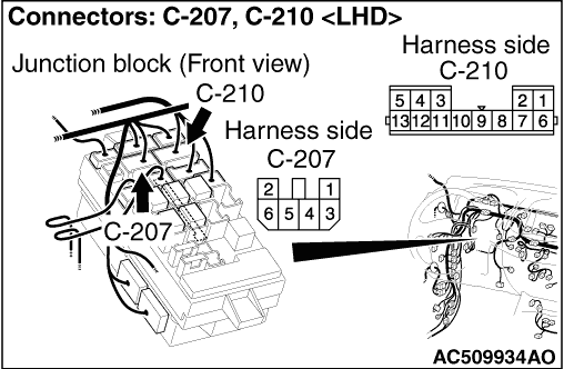
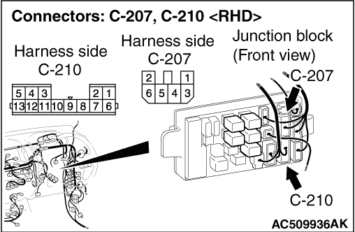
(1)Disconnect the C-210 junction block connector.
|
|
|
(2)Disconnect the fusible link No.21 and No.22.
|
|
|
(3)Disconnect the A-01 ABS-ECU connector, and measure at the wiring harness-side connector.
|
|
|
(4)Measure the resistance between the A-01 ABS-ECU connector terminal No.1, No.13, No.25 and the body earth.
OK: No continuity
|
|
|
Q.
Is the check result normal?
|
|
|
The short circuit may be present in the power supply circuit. Repair the wiring harness between the A-01 ABS-ECU connector terminal No.1, No.13, No.25 and the fusible link No.21, No.22, the C-210 junction block connector terminal No.8. Then go to Step 10.
|
|
|
|
|
|
(1)Disconnect the A-01 ABS-ECU connector.
|
|
|
(2)Turn the ignition switch to the "ON" position.
|
|
|
(3)Measure the resistance between the A-01 ABS-ECU connector terminal No.1, No.13, No.25 and the body earth.
OK: Battery voltage
|
|
|
Q.
Is the check result normal?
|
|
|
The open circuit may be present in the power supply circuit. Repair the wiring harness between the A-01 ABS-ECU connector terminal No.1, No.13, No.25 and the fusible link No.21, No.22, the C-210 junction block connector terminal No.8. Then go to Step 10.
|
|
|
|
|
|
(1)Erase the diagnosis code.
|
|
|
(2)Turn the ignition switch to the "LOCK" (OFF) position.
|
|
|
(3)Turn the ignition switch to the "ON" position.
|
|
|
(4)Check if the diagnosis code is set.
|
|
|
Q.
Is diagnosis code No. C1861 set?
|
|
|
 Replace the hydraulic unit (integrated with ABS-ECU) (Refer to .). Then go to Step 10. Replace the hydraulic unit (integrated with ABS-ECU) (Refer to .). Then go to Step 10.
|
|
|
|
|
|
Intermittent malfunction (Refer to GROUP 00 - How to Cope with Intermittent Malfunctions .).
|
|
|
|
|
|
(1)Erase the diagnosis code.
|
|
|
(2)Turn the ignition switch to the "LOCK" (OFF) position.
|
|
|
(3)Turn the ignition switch to the "ON" position.
|
|
|
(4)Check if the diagnosis code is set.
|
|
|
Q.
Is diagnosis code No. C1861 set?
|
|
|
This diagnosis is complete.
|
|
|
|