|
|
Use M.U.T.-III to diagnose the CAN bus lines.
|
|
|
Q.
Is the check result normal?
|
|
|
 Repair the CAN bus lines (Refer to GROUP 54C - CAN Bus Diagnostics Table Repair the CAN bus lines (Refer to GROUP 54C - CAN Bus Diagnostics Table  .).
On completion, go to Step 2. .).
On completion, go to Step 2.
|
|
|
|
|
|
(1)Erase the diagnosis code.
|
|
|
(2)Drive the vehicle at 15 km/h or more.
| note |
The ABS warning lamp does not turn OFF in some cases unless the vehicle runs at 15 km/h
or higher.
|
|
|
|
Q.
Is the diagnosis code No.C1211 set?
|
|
|
This diagnosis is complete.
|
|
|
|
|
|
Check that the diagnosis codes No.C1210 or C1212 is also set.
|
|
|
Q.
Are the diagnosis codes No.C1210 or C1212 also set?
|
|
|
 Perform the diagnosis for the diagnosis codes No.C1210 (Refer to ). Perform the diagnosis for the diagnosis codes No.C1210 (Refer to ).
|
|
|
|
|
|
Check the following data list (Refer to .).
|
|
|
- Item No.04: RR wheel speed sensor
|
|
|
Q.
Is the check result normal?
|
|
|
Check how the wheel speed sensor (RR) is installed correctly (Disconnection of wheel speed
sensor (RR), loose mounting bolt, etc.).
|
|
|
Q.
Is the check result normal?
|
|
|
Reinstall the wheel speed sensor (RR) correctly (Refer to .).
Then go to Step 13.
|
|
|
|
|
|
Q.
Is the check result normal?
|
|
|
Replace the wheel speed sensor (RR) (Refer to .).
Then go to Step 13.
|
|
|
|
|
|
Q.
Is the check result normal?
|
|
|
Replace the rear axle shaft bearing (Refer to GROUP 27, Axle shaft assembly .).
Then go to Step 13.
|
|
|
|
|
|
Check the ABS rotor (RR), which diagnosis code indicates, for foreign material or deformation.
|
|
|
Q.
Is the check result normal?
|
|
|
If the ABS rotor (RR) is contaminated with foreign material, clean it. If the
rear axle shaft bearing is deformed, replace it (Refer to GROUP 27, Axle shaft assembly .).
Then go to Step 13.
|
|
|
|
|
|
Q.
Is the check result normal?
|
|
|
Repair the defective connector. Then go to Step 13.
|
|
|
|
|
|
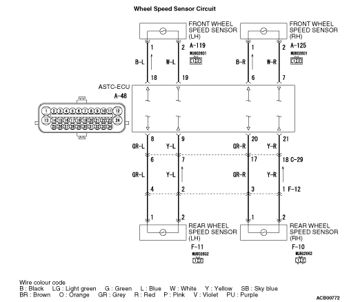
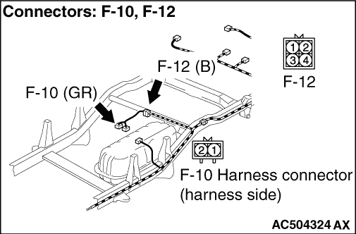
(1)Disconnect the A-48 ASTC-ECU connector, the F-10 rear wheel speed sensor (RH) connector.
|
|
|
(2)Measure the voltage between the A-48 ASTC-ECU connector terminal No.21 and body
earth.
OK: 1V or less
|
|
|
Q.
Is the check result normal?
|
|
|
Repair the harness wire. Then go to Step 13.
|
|
|
|
|
|
(1)Disconnect the F-10 rear wheel speed sensor (RH) connector, and measure the resistance
at the harness connector side.
|
|
|
(2)Disconnect the A-48 ASTC-ECU connector.
|
|
|
(3)Measure the resistance between the A-48 ASTC-ECU connector terminal No.21 and body
earth.
OK: No continuity
|
|
|
Q.
Is the check result normal?
|
|
|
Repair the harness wire. Then go to Step 13.
|
|
|
|
|
|
(1)Erase the diagnosis code.
|
|
|
(2)Drive the vehicle at 15 km/h or more.
| note |
The ABS warning lamp does not turn OFF in some cases unless the vehicle runs at 15 km/h
or higher.
|
|
|
|
Q.
Is the diagnosis code No.C1211 set?
|
|
|
Replace the hydraulic unit (integrated with ASTC-ECU) (Refer to .).
Then go to Step 13.
|
|
|
|
|
|
Intermittent malfunction (Refer to GROUP 00 - How to Cope with Intermittent
Malfunctions .).
|
|
|
|
|
|
(1)Erase the diagnosis code.
|
|
|
(2)Drive the vehicle at 15 km/h or more.
| note |
The ABS warning lamp does not turn OFF in some cases unless the vehicle runs at 15 km/h
or higher.
|
|
|
|
Q.
Is the diagnosis code No.C1211 set?
|
|
|
This diagnosis is complete.
|
|
|
|