Code No.C1223: G and yaw rate sensor (active check error)
|
|
| caution |
If there is any problem in the CAN bus lines, an incorrect diagnosis code may be set. Diagnose the CAN bus lines before the diagnosis code (Refer to GROUP 54C - CAN Bus Diagnostics Table  ). ).
|
|
|
|
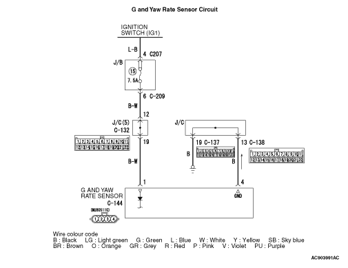
- The G and yaw rate sensor is energized by the ignition switch (IG1) and the G and yaw rate sensor terminal 1.
- The G and yaw rate sensor output signal is sent to the ASTC-ECU via the private CAN bus line.
|
|
|
DIAGNOSIS CODE SET CONDITION
|
|
|
The diagnosis code is set if the first G and yaw rate sensor check is not completed within the specified time although ASTC-ECU input voltage is normal when the ignition switch is turned ON.
|
|
|
- Malfunction of the G and yaw rate sensor
- Damaged wiring harness or connector
- Malfunction of the hydraulic unit (integrated with ASTC-ECU)
|
|
|
STEP 1. M.U.T.-III CAN bus diagnosis
|
|
|
Use M.U.T.-III to diagnose the CAN bus lines.
|
|
|
Q.
Is the check result normal?
|
|
|
 Go to Step 3. Go to Step 3.
|
|
|
|
|
|
 Repair the CAN bus lines (Refer to GROUP 54C - CAN Bus Diagnostics table ). On completion, go to Step 2. Repair the CAN bus lines (Refer to GROUP 54C - CAN Bus Diagnostics table ). On completion, go to Step 2.
|
|
|
|
|
|
STEP 2. Diagnosis code recheck after resetting CAN bus lines
|
|
|
Q.
Is the diagnosis code No.C1223 set?
|
|
|
Go to Step 3.
|
|
|
|
|
|
This diagnosis is complete.
|
|
|
|
|
|
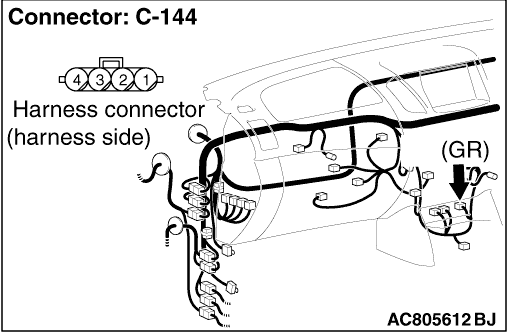
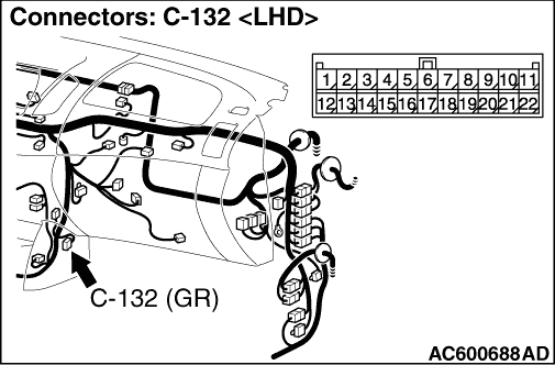
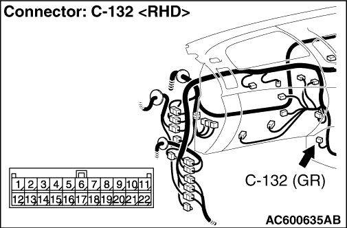
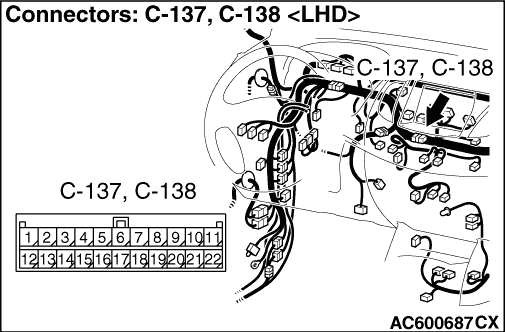
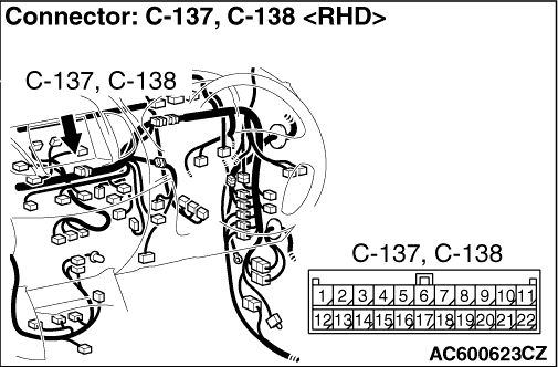
STEP 3. Connector check: C-144 G and yaw rate sensor connector, C-132 joint connector, C-137 joint connector and C-138 joint connector
|
|
|
Q.
Is the check result normal?
|
|
|
Go to Step 4.
|
|
|
|
|
|
Repair the defective connector. Then go to Step 9.
|
|
|
|
|
|
STEP 4. Resistance measurement at the C-144 G and yaw rate sensor connector
|
|
|
(1)Disconnect the connector C-144 G and yaw rate sensor connector and measurement at the harness-side connector.
|
|
|
(2)Measure the resistance between the C-144 G and yaw rate sensor connector terminal No.4 and body earth.
OK: Continuity exists (2 Ω or less)
|
|
|
Q.
Is the check result normal?
|
|
|
Go to Step 6.
|
|
|
|
|
|
Go to Step 5.
|
|
|
|
|
|
STEP 5. Resistance measurement at the C-137 joint connector
|
|
|
(1)Disconnect the connector C-137 joint connector and measurement at the harness-side connector.
|
|
|
(2)Measure the resistance between the C-144 G and yaw rate sensor connector terminal No.19 and body earth.
OK: Continuity exists (2 Ω or less)
|
|
|
Q.
Is the check result normal?
|
|
|
An open circuit may be present. Repair the harness wire between C-138 joint connector terminal No.13 and C-144 G and yaw rate sensor connector terminal No.4. Then go to Step 9.
|
|
|
|
|
|
An open circuit may be present. Repair the harness wire between C-137 joint connector terminal No.19 and body earth. Then go to Step 9.
|
|
|
|
|
|
STEP 6. Voltage measurement at the C-144 G and yaw rate sensor connector
|
|
|
(1)Disconnect the connector C-144 G and yaw rate sensor connector and measurement at the harness-side connector.
|
|
|
(2)Turn the ignition switch to the "ON" position.
|
|
|
(3)Measure the voltage between the C-144 G and yaw rate sensor connector terminal No.1 and body earth.
OK: System voltage
|
|
|
Q.
Is the check result normal?
|
|
|
Go to Step 7.
|
|
|
|
|
|
An open circuit may be present. Repair the wiring harness between the C-144 G and yaw rate sensor connector terminal No.1 and the C-132 joint connector terminal No.19. Then go to Step 9.
|
|
|
|
|
|
STEP 7. Check whether the diagnosis code is reset.
|
|
|
Check again if the diagnosis code is set.
|
|
|
(1)Turn the ignition switch to the "ON" position.
|
|
|
(2)Erase the diagnosis code.
|
|
|
(3)Turn the ignition switch to the "LOCK" (OFF) position.
|
|
|
(4)Turn the ignition switch to the "ON" position.
|
|
|
(5)Check if the diagnosis code is set.
|
|
|
(6)Turn the ignition switch to the "LOCK" (OFF) position.
|
|
|
Replace the G and yaw rate sensor (Refer to ). Then go to Step 8.
|
|
|
|
|
|
Intermittent malfunction (Refer to GROUP 00 - How to Cope with Intermittent Malfunction ).
|
|
|
|
|
|
STEP 8. Check whether the diagnosis code is reset.
|
|
|
Check again if the diagnosis code is set.
|
|
|
(1)Turn the ignition switch to the "ON" position.
|
|
|
(2)Erase the diagnosis code.
|
|
|
(3)Turn the ignition switch to the "LOCK" (OFF) position.
|
|
|
(4)Turn the ignition switch to the "ON" position.
|
|
|
(5)Check if the diagnosis code is set.
|
|
|
(6)Turn the ignition switch to the "LOCK" (OFF) position.
|
|
|
Replace the hydraulic unit (integrated with ASTC-ECU) (Refer to ). Then go to Step 9.
|
|
|
|
|
|
The procedure is complete.
|
|
|
|
|
|
STEP 9. Recheck for diagnosis code.
|
|
|
Check again if the diagnosis code is set.
|
|
|
(1)Turn the ignition switch to the "ON" position.
|
|
|
(2)Erase the diagnosis code.
|
|
|
(3)Turn the ignition switch to the "LOCK" (OFF) position.
|
|
|
(4)Turn the ignition switch to the "ON" position.
|
|
|
(5)Check if the diagnosis code is set.
|
|
|
(6)Turn the ignition switch to the "LOCK" (OFF) position.
|
|
|
Go to Step 1.
|
|
|
|
|
|
The procedure is complete.
|
|
|
|