|
|
Use M.U.T.-III to diagnose the CAN bus lines.
|
|
|
Q.
Is the check result normal?
|
|
|
 Repair the CAN bus lines (Refer to GROUP 54C - CAN Bus Diagnostics Table  .). Then go to Step 6.
|
|
|
|
|
|
Q.
Is the check result normal?
|
|
|
Repair or replace it. Then go to Step 6.
|
|
|
|
|
|
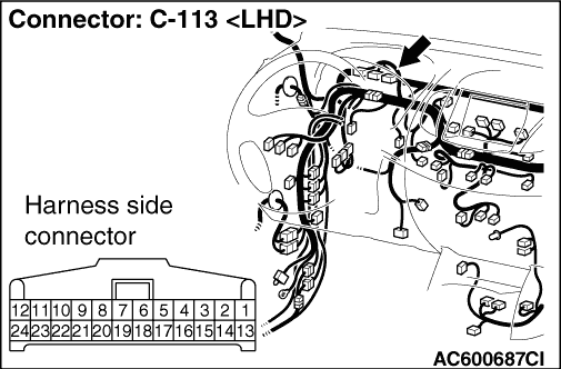
Check for open circuit in the wiring harness between A-48 ASTC-ECU connector terminal No.10 and C-113 combination meter connector terminal No.32.
|
|
|
Q.
Is the check result normal?
|
|
|
Repair the wiring harness between the A-48 ASTC-ECU terminal No.10 and the C-113 combination meter connector terminal No.32. Then go to Step 6.
|
|
|
|
|
|
Q.
Is any diagnosis code set?
|
|
|
 Refer to Diagnosis Code Chart (Refer to .). Then go to Step 6.
|
|
|
|
|
|
Replace the combination meter assembly (Refer to GROUP 54A, Combination Meter .). Then go to Step 5.
|
|
|
|
|
|
Q.
Turn the ignition switch to the "ON" position. Does the ASTC OFF indicator lamp illuminate for three seconds, and then go out after the engine starts?
|
|
|
The procedure is complete.
|
|
|
|
|
|
Replace the hydraulic unit (integrated with ASTC-ECU) (Refer to .). Then go to Step 6.
|
|
|
|
|
|
Q.
Turn the ignition switch to the "ON" position. Does the ASTC OFF indicator lamp illuminate for three seconds, and then go out after the engine starts?
|
|
|
The procedure is complete.
|
|
|
|