|
|
Use M.U.T.-III to diagnose the CAN bus lines.
|
|
|
Q.
Is the check result normal?
|
|
|
 Repair the CAN bus lines (Refer to GROUP 54C - CAN Bus Diagnostics Table Repair the CAN bus lines (Refer to GROUP 54C - CAN Bus Diagnostics Table  .).
On completion, go to Step 2. .).
On completion, go to Step 2.
|
|
|
|
|
|
(1)Erase the diagnosis code.
|
|
|
(2)Drive the vehicle at 15 km/h or more.
| note |
The ABS warning lamp does not turn OFF in some cases unless the vehicle runs at 15 km/h
or higher.
|
|
|
|
Q.
Is the diagnosis code No.C1207 set?
|
|
|
This diagnosis is complete.
|
|
|
|
|
|
Check the following data list (Refer to .
|
|
|
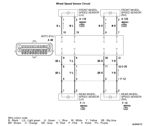
- Item No.01: FL wheel speed sensor
|
|
|
Q.
Is the check result normal?
|
|
|
Q.
Is the check result normal?
|
|
|
Repair the defective connector. Then go to Step 9.
|
|
|
|
|
|
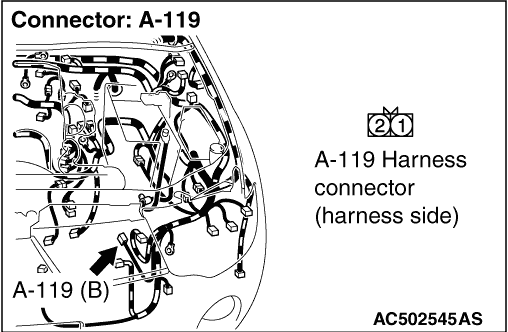
(1)Disconnect the A-48 ASTC-ECU connector, the A-119 front wheel speed sensor (LH)
connector.
|
|
|
(2)Measure the voltage between the A-48 ASTC-ECU connector terminal No.18 and body
earth.
OK: 1V or less
|
|
|
Q.
Is the check result normal?
|
|
|
Repair the wiring harness. Then go to Step 9.
|
|
|
|
|
|
(1)Disconnect the A-48 ASTC-ECU connector, the A-119 front wheel speed sensor connector.
|
|
|
(2)Measure the resistance between the A-48 ASTC-ECU connector terminal No.18 and body
earth.
OK: No continuity
|
|
|
Q.
Is the check result normal?
|
|
|
Repair the wiring harness. Then go to Step 9.
|
|
|
|
|
|
Q.
Is the check result normal?
|
|
|
Replace the wheel speed sensor (Refer to .). Then
go to Step 9.
|
|
|
|
|
|
(1)Erase the diagnosis code.
|
|
|
(2)Drive the vehicle at 15 km/h or more.
| note |
The ABS warning lamp does not turn OFF in some cases unless the vehicle runs at 15 km/h
or higher.
|
|
|
|
Q.
Is the diagnosis code No.C1207 set?
|
|
|
 Replace the hydraulic unit (integrated with ASTC-ECU) (Refer to .).
Then go to Step 9. Replace the hydraulic unit (integrated with ASTC-ECU) (Refer to .).
Then go to Step 9.
|
|
|
|
|
|
Intermittent malfunction (Refer to GROUP 00 - How to Cope with Intermittent
Malfunctions .).
|
|
|
|
|
|
(1)Erase the diagnosis code.
|
|
|
(2)Drive the vehicle at 15 km/h or more.
| note |
The ABS warning lamp does not turn OFF in some cases unless the vehicle runs at 15 km/h
or higher.
|
|
|
|
Q.
Is the diagnosis code No.C1207 set?
|
|
|
This diagnosis is complete.
|
|
|
|