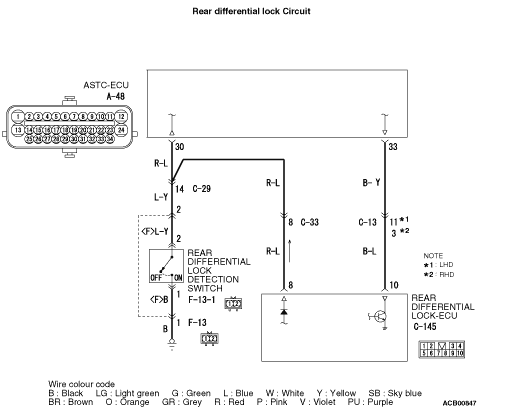
Code No.C1293: Abnormal rear differential lock detection circuit <Vehicle with rear differential lock system>

| caution |
- If there is any problem in the CAN bus lines, an incorrect diagnosis code may be set. Diagnose the CAN bus lines before the diagnosis codes (Refer to GROUP 54C - CAN Bus Diagnostics Table
 .). .).
- Whenever the ECU is replaced, ensure that the communication circuit is normal.
|
OPERATION
- Rear differential lock detection switch: "ON"
- Rear differential lock indicator lamp: illuminates or flashes
DIAGNOSIS CODE SET CONDITIONS
- Rear differential lock detection switch: "ON", Rear differential lock indicator signal: When the "OFF" signal is received for a certain period at the same time
- Rear differential lock detection switch: "OFF", Rear differential lock indicator signal: When the "ON" signal is received for a certain period at the same time
PROBABLE CAUSES
- Damaged wiring harness or connector
- Malfunction of rear differential lock detection switch
- Malfunction of rear differential lock-ECU
- Malfunction of ASTC-ECU
|
|
STEP 1. M.U.T.-III CAN bus diagnostics
|
|
|
Use M.U.T.-III to diagnose the CAN bus lines.
|
|
|
Q.
Is the check result normal?
|
|
|
 Go to Step 3. Go to Step 3.
|
|
|
|
|
|
 Repair the CAN bus line (Refer to GROUP 54C - CAN Bus Diagnostics Table .). Then go to Step 2. Repair the CAN bus line (Refer to GROUP 54C - CAN Bus Diagnostics Table .). Then go to Step 2.
|
|
|
|
|
|
STEP 2. Check whether the diagnosis code is reset.
|
|
|
(1)Turn the ignition switch to the "ON" position.
|
|
|
(2)Erase the diagnosis code.
|
|
|
(3)Turn the ignition switch to the "LOCK" (OFF) position.
|
|
|
(4)Turn the ignition switch to the "ON" position.
|
|
|
(6)Turn the rear differential lock switch to the "ON" position.
|
|
|
(7)Drive the vehicle more than 10 seconds at the speed exceeds 10 km/h.
|
|
|
(8)Check if the diagnosis code is set.
|
|
|
Go to Step 3.
|
|
|
|
|
|
The procedure is complete.
|
|
|
|
|
|
STEP 3. Check the M.U.T.-III data list.
|
|
|
(1)Turn the ignition switch to the "ON" position.
|
|
|
(2)Operate the rear differential lock switch, and check if the operation status matches the data list output.
- Item No.63: Rear differential lock switch
OK:
(Rear differential lock switch: ON): ON
(Rear differential lock switch: OFF): OFF
|
|
|
Q.
Is the check result normal?
|
|
|
Go to Step 13.
|
|
|
|
|
|
Go to Step 4.
|
|
|
|
|
|
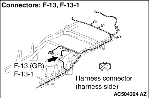
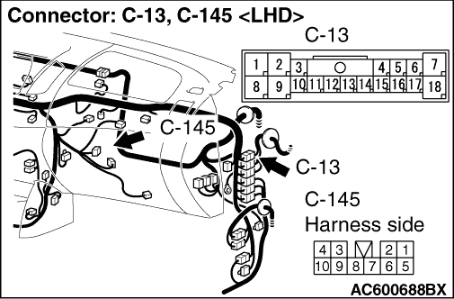
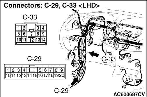
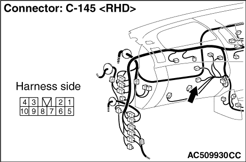
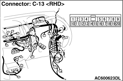
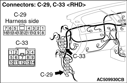
STEP 4. Connector check: A-48 ASTC-ECU connector, F-13-1 rear differential lock detection switch connector, C-145 rear differential lock-ECU connector, C-13 intermediate connector, C-29 intermediate connector, C-33 intermediate connector, F-13 intermediate connector.
|
|
|
Q.
Is the check result normal?
|
|
|
Go to Step 5.
|
|
|
|
|
|
Repair or replace the damaged component(s). Then go to Step 15.
|
|
|
|
|
|
STEP 5. Rear differential lock detection switch check
|
|
|
Refer to GROUP 27 - On-vehicles service, Rear differential Lock Detection Switch Check .
|
|
|
Q.
Is the check result normal?
|
|
|
Go to Step 6.
|
|
|
|
|
|
Replace the Rear differential lock detection switch (Refer to GROUP 27 - Rear differential lock .). Then go to Step 15.
|
|
|
|
|
|
STEP 6. Resistance measurement at the C-145 rear differential lock-ECU connector
|
|
|
(1)Disconnect the C-145 rear differential lock-ECU connector and measure the resistance at the harness side.
|
|
|
(2)Disconnect the A-48 ASTC-ECU connector.
|
|
|
(3)Measure the resistance between the C-145 rear differential lock-ECU connector terminal No.10 and body earth.
OK: No continuity
|
|
|
Q.
Is the check result normal?
|
|
|
Go to Step 7.
|
|
|
|
|
|
Repair the wiring harness. Then go to Step 15.
|
|
|
|
|
|
STEP 7. Voltage measurement at the C-145 rear differential lock-ECU connector
|
|
|
(1)Disconnect the C-145 rear differential lock-ECU connector and measure the voltage at the harness side.
|
|
|
(2)Disconnect the A-48 ASTC-ECU connector.
|
|
|
(3)Measure the voltage between the C-145 rear differential lock-ECU connector terminal No.10 and body earth.
OK: 1 V or less
|
|
|
Q.
Is the check result normal?
|
|
|
Go to Step 8.
|
|
|
|
|
|
Repair the wiring harness. Then go to Step 15.
|
|
|
|
|
|
STEP 8. Resistance measurement at the A-48 ASTC-ECU connector and C-145 rear differential lock-ECU connector
|
|
|
(1)Disconnect the A-48 ASC-ECU connector.
|
|
|
(2)Disconnect the C-145 rear differential lock-ECU connector.
|
|
|
(3)Measure the resistance between the A-48 ASTC-ECU connector terminal No.33 and C-145 rear differential lock-ECU connector terminal No.10.
OK: Continuity exists (2 Ω or less)
|
|
|
Q.
Is the check result normal?
|
|
|
Go to Step 9.
|
|
|
|
|
|
Repair the wiring harness. Then go to Step 15.
|
|
|
|
|
|
STEP 9. Resistance measurement at the C-145 rear differential lock-ECU connector
|
|
|
(1)Disconnect the C-145 rear differential lock-ECU connector and measure the resistance at the harness side.
|
|
|
(2)Disconnect the A-48 ASTC-ECU connector and F-13-1 rear differential lock detection switch connector.
|
|
|
(3)Measure the resistance between the C-145 rear differential lock-ECU connector terminal No.8 and body earth.
OK: No continuity
|
|
|
Q.
Is the check result normal?
|
|
|
Go to Step 10.
|
|
|
|
|
|
Repair the wiring harness. Then go to Step 15.
|
|
|
|
|
|
STEP 10. Resistance measurement at the A-48 ASTC-ECU connector and C-145 rear differential lock-ECU connector
|
|
|
(1)Disconnect the A-48 ASTC-ECU connector.
|
|
|
(2)Disconnect the C-145 rear differential lock-ECU connector.
|
|
|
(3)Measure the resistance between the A-48 ASTC-ECU connector terminal No.30 and C-145 rear differential lock-ECU connector terminal No.8.
OK: Continuity exists (2 Ω or less)
|
|
|
Q.
Is the check result normal?
|
|
|
Go to Step 11.
|
|
|
|
|
|
Repair the wiring harness. Then go to Step 15.
|
|
|
|
|
|
STEP 11. Resistance measurement at the A-48 ASTC-ECU connector and F-13-1 rear differential lock detection switch connector
|
|
|
(1)Disconnect the A-48 ASTC-ECU connector.
|
|
|
(2)Disconnect the F-13-1 rear differential detection switch connector.
|
|
|
(3)Measure the resistance between the A-48 ASTC-ECU connector terminal No.30 and F-13-1 rear differential detection switch connector terminal No.2.
OK: Continuity exists (2 Ω or less)
|
|
|
Q.
Is the check result normal?
|
|
|
Go to Step 12.
|
|
|
|
|
|
Repair the wiring harness. Then go to Step 15.
|
|
|
|
|
|
STEP 12. Resistance measurement at the F-13-1 rear differential lock detection switch connector
|
|
|
(1)Disconnect the F-13-1 rear differential lock detection switch connector and measure the resistance at the harness side.
|
|
|
(2)Measure the resistance between the F-13-1 rear differential lock detection switch connector terminal No.1 and body earth.
OK: Continuity exists (2 Ω or less)
|
|
|
Q.
Is the check result normal?
|
|
|
Go to Step 13.
|
|
|
|
|
|
Repair the wiring harness. Then go to Step 15.
|
|
|
|
|
|
STEP 13. Check whether the diagnosis code is reset.
|
|
|
(1)Turn the ignition switch to the "ON" position.
|
|
|
(2)Erase the diagnosis code.
|
|
|
(3)Turn the ignition switch to the "LOCK" (OFF) position.
|
|
|
(4)Turn the ignition switch to the "ON" position.
|
|
|
(6)Turn the rear differential lock switch to the "ON" position.
|
|
|
(7)Drive the vehicle more than 10 seconds at the speed exceeds 10 km/h.
|
|
|
(8)Check if the diagnosis code is set.
|
|
|
Replace the Rear differential lock-ECU (Refer to GROUP 27 - Rear differential lock-ECU .). Then go to Step 14.
|
|
|
|
|
|
Intermittent malfunction (Refer to GROUP 00 - How to Cope with Intermittent Malfunctions .).
|
|
|
|
|
|
STEP 14. Check whether the diagnosis code is reset.
|
|
|
(1)Turn the ignition switch to the "ON" position.
|
|
|
(2)Erase the diagnosis code.
|
|
|
(3)Turn the ignition switch to the "LOCK" (OFF) position.
|
|
|
(4)Turn the ignition switch to the "ON" position.
|
|
|
(6)Turn the rear differential lock switch to the "ON" position.
|
|
|
(7)Drive the vehicle more than 10 seconds at the speed exceeds 10 km/h.
|
|
|
(8)Check if the diagnosis code is set.
|
|
|
Replace the hydraulic unit assembly (integrated with ASTC-ECU) (Refer to .). Then go to Step 15.
|
|
|
|
|
|
This diagnosis is complete.
|
|
|
|
|
|
STEP 15. Check whether the diagnosis code is reset.
|
|
|
(1)Turn the ignition switch to the "ON" position.
|
|
|
(2)Erase the diagnosis code.
|
|
|
(3)Turn the ignition switch to the "LOCK" (OFF) position.
|
|
|
(4)Turn the ignition switch to the "ON" position.
|
|
|
(6)Turn the rear differential lock switch to the "ON" position.
|
|
|
(7)Drive the vehicle more than 10 seconds at the speed exceeds 10 km/h.
|
|
|
(8)Check if the diagnosis code is set.
|
|
|
Return to Step 1.
|
|
|
|
|
|
This diagnosis is complete.
|
|
|
|